


 English
 中文简体
中文简体 русский
10kV Overhead Insulated Cable Tree Guide
10kV Overhead Insulated Cable Tree Guide
10kV Overhead Insulated Cable Tree Guide
10kV Overhead Insulated Cable Tree Guide
10kV Overhead Insulated Cable Tree Guide
10kV Overhead Insulated Cable Tree Guide
10kV Overhead Insulated Cable Tree Guide
10kV Overhead Insulated Cable Tree Guide
10kV Overhead Insulated Cable Tree Guide
10kV Overhead Insulated Cable Tree Guide
10kV Overhead Insulated Cable Tree Guide
10kV Overhead Insulated Cable Tree Guide
10kV Overhead Insulated Cable Tree Guide
10kV Overhead Insulated Cable Tree Guide
10kV Overhead Insulated Cable Tree Guide
10kV Overhead Insulated Cable Tree Guide
Industry News
Product Category
NEW Category
Contact us
 +86-0510-87296815
10kV Overhead Insulated Cable Tree Guide
Content
Understanding Insulation Types and Tree Contact Tolerances
The modernization of urban and rural power grids has necessitated a significant shift from traditional bare conductors to insulated alternatives. This transition is primarily driven by the need to improve safety, reduce fault rates caused by wildlife or falling branches, and achieve the aesthetic goals of an "invisible power grid." However, routing these lines through heavily wooded areas or established urban canopies presents unique engineering challenges. When deploying a 10kV overhead insulated cable network, line contractors and utility engineers must navigate complex clearance requirements and understand the specific tolerances for vegetation contact. Unlike bare wires, which demand aggressive and continuous tree trimming to maintain strict air gaps, insulated cables offer a degree of forgiveness. Yet, this does not imply that installation near trees can be done without rigorous planning.
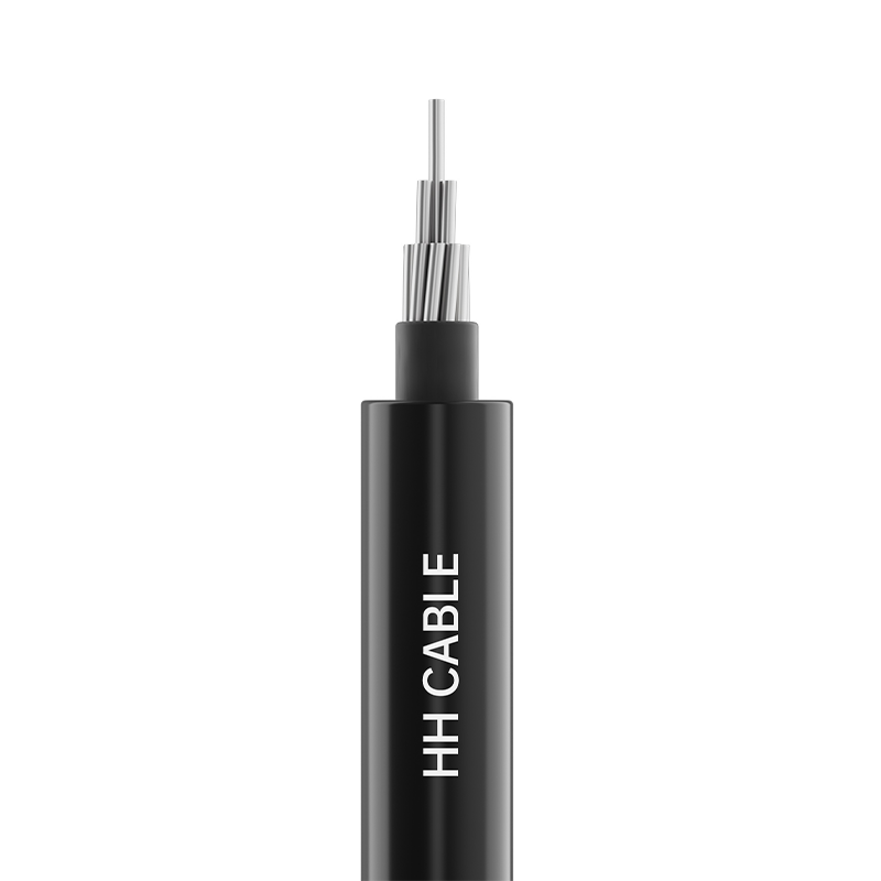
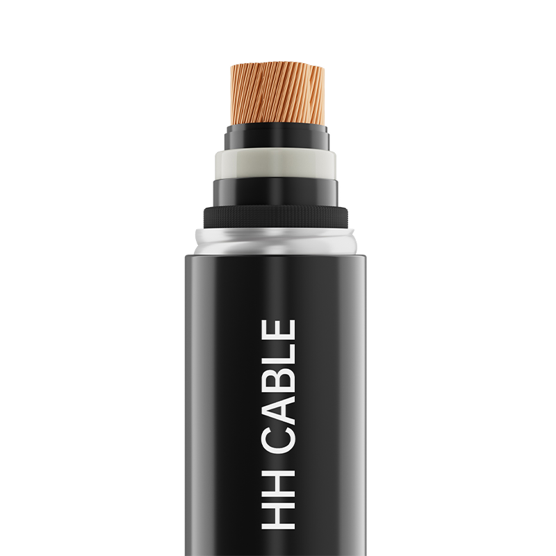
Not all insulated cables are manufactured with the same thickness or material composition, and this directly dictates how they interact with surrounding vegetation. Utility standards generally categorize these cables based on their insulation robustness, which determines whether tree contact is permissible during high winds or growth cycles. Light or thin-insulated cables are designed primarily for short spans and areas where vegetation is strictly managed. When installing these overhead, a substantial physical distance must be maintained from all tree limbs. During operation, only brief, accidental, and short-term contact between the cable and trees is allowable. Prolonged rubbing will quickly degrade the thin polymer layer, leading to partial discharge and eventual failure.
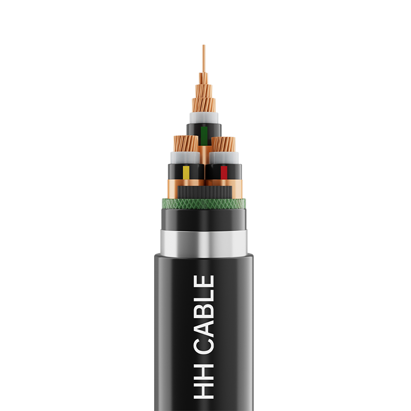
Conversely, natural or weather-resistant insulated cables feature a thicker, more robust polymer jacket designed to withstand environmental stressors. For these cables, while a certain initial clearance distance should still be maintained during the stringing process, frequent and sustained contact between the cables and trees is permitted during normal operation and wind sway events. Standard thick-insulated cables offer the highest level of mechanical protection. These are typically installed in fixed overhead locations where right-of-way constraints are severe. Frequent contact with trees is permitted, but the constant mechanical abrasion from branches can still eventually compromise the outer sheath, necessitating specialized hardware to mitigate wear.
| Insulation Category | Material Composition | Allowable Tree Contact | Primary Application |
| Light / Thin Insulation | HDPE / Thin XLPE | Short-term only | Managed rural corridors |
| Natural / Weather-Resistant | Thick XLPE | Frequent contact allowed | Suburban and wooded areas |
| Standard Thick Insulation | Heavy-duty XLPE | Continuous contact allowed | Dense urban canopies |
Pre-Installation Planning and Route Surveying
Before any physical installation begins, a meticulous route survey is mandatory when working near vegetation. Trees are dynamic structures; they grow vertically and laterally, and their branches sway significantly under wind and ice loads. Engineers must calculate the maximum anticipated sway of both the tree canopy and the 10kV overhead insulated cable to ensure that dynamic clearances are never violated in a way that causes excessive mechanical stress on the line hardware. When surveying, identify fast-growing tree species that will rapidly encroach on the right-of-way within a three-to-five-year maintenance cycle. Furthermore, consider the seasonal variations in foliage weight, which can cause branches to sag closer to the conductors during wet seasons.

Calculating Wind Sway and Growth Margins
To establish a safe initial installation distance, contractors must apply a dynamic clearance formula. This involves taking the static required clearance and adding a margin for maximum conductor blowout in high winds, plus a margin for tree branch blowout toward the line. If the sum of these dynamic movements exceeds the physical gap, the tree must be pruned prior to installation, or the pole alignment must be adjusted. Relying solely on the insulation to handle constant, high-force branch impact is a poor engineering practice that leads to premature hardware fatigue and potential insulation chafing over the operational lifespan of the grid.
Installation Clearances and Bending Radius Constraints
The physical handling of the cable during the stringing process near trees requires strict adherence to mechanical limits to prevent invisible damage to the insulation layer. Navigating through tight canopy gaps often tempts contractors to pull the cable at sharp angles around branches or use excessive force, which can compromise the dielectric integrity of the 10kV overhead insulated cable. The most critical mechanical constraint is the minimum bending radius. Violating this parameter causes micro-cracking in the insulation, which accelerates water treeing and electrical failure when exposed to moisture from nearby foliage.
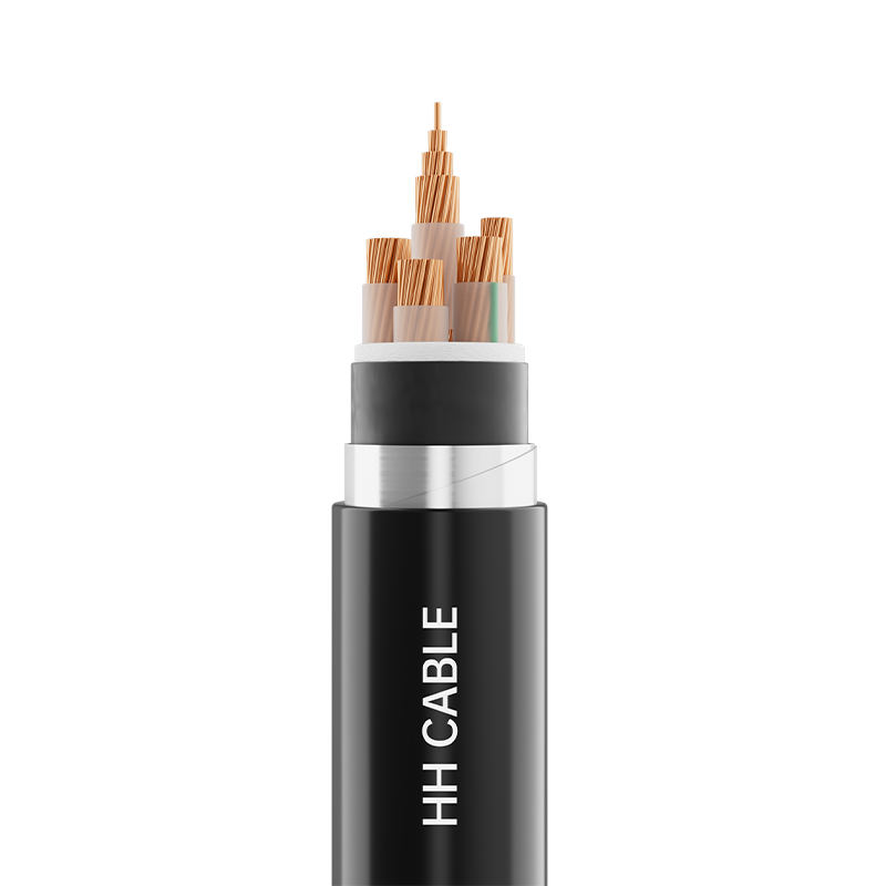
- Single-core cables: The minimum bending radius must strictly not be less than 20 times the outer diameter of the cable. This generous radius is required because single-core constructions lack the internal structural support of multiple cores, making the insulation highly susceptible to deformation and internal electrical stress concentration if bent too sharply around obstacles like tree limbs.
- Multi-core cables: The minimum bending radius must not be less than 15 times the outer diameter of the cable. The bundled nature of multi-core designs provides slightly more structural rigidity, allowing for a marginally tighter bending radius when navigating complex canopy routes, though extreme care must still be taken to avoid damaging the outer sheath.
- Tension limits during stringing: When pulling the cable through wooded corridors, the maximum pulling tension must never exceed the manufacturer's specified limits. Using a swivel joint and a calibrated dynamometer ensures that sudden snags on hidden branches do not apply catastrophic tensile forces that could stretch the aluminum conductor and permanently thin the insulation layer.
Furthermore, environmental conditions during installation play a vital role. The ambient temperature during cable stringing must not be lower than -20°C. In colder environments, the polymer insulation becomes brittle, and pulling the cable through tight, branch-filled corridors will result in severe surface scoring or cracking. If installation must occur in sub-zero temperatures, the cable must be pre-heated in a warm enclosure before being transported to the site and immediately strung to preserve the material's flexibility.
Hardware Selection and Tree-Friendly Mounting
The choice of suspension and strain hardware is paramount when the line is in close proximity to trees. Standard metal clamps can act as abrasion points if a branch constantly rubs against the hardware-cable junction. For installations where frequent tree contact is anticipated, contractors should utilize specialized, smooth-profile suspension clamps with integrated elastomeric grips. These grips distribute the mechanical load evenly around the circumference of the cable, preventing localized stress concentrations that could be exacerbated by branch impacts. Additionally, when routing the line down to ground-mounted equipment, such as pad-mounted transformers located near shrubbery or small trees, standard rigid aluminum conductors are unsuitable. In these specific downlead applications, soft copper core overhead insulated cables must be utilized. The high flexibility of the stranded soft copper allows the cable to absorb wind-induced vibrations and minor branch impacts without transferring destructive mechanical forces to the transformer bushings or the termination points.
Long-Term Maintenance and Vegetation Management
While the primary advantage of deploying a 10kV overhead insulated cable is the reduction in immediate vegetation management costs, it does not eliminate the need for long-term forestry planning. Constant mechanical abrasion from tree branches, combined with UV exposure and biological growth like moss or lichen, can slowly degrade the outer weather-resistant jacket over a decade or more. Utility maintenance crews should implement a cyclical inspection program focusing specifically on spans where tree contact is known to be frequent. Inspectors must look for signs of "chafing," where the outer black weather-resistant layer has been worn away, exposing the underlying inner layers or the conductor shield.
If chafing is detected, the affected span must be scheduled for replacement, or the offending vegetation must be pruned back to establish a permanent air gap. Furthermore, keeping the area around pole bases clear of climbing vines is essential, as vines can use the cables as a trellis, eventually engulfing the line and retaining moisture against the insulation, which drastically accelerates the aging process. By combining the inherent safety of insulated cables with proactive, targeted vegetation management, utilities can achieve a highly reliable, aesthetically pleasing, and safe power distribution network that harmonizes with the natural environment.
PREV:XLPE Insulated Control Cable 450/750V: Specs, Types & Installation Guide
NEXT:Overhead Insulated Cable and XLPE Insulated Cable: A Complete Guide for Modern Power Distribution
NEXT:Overhead Insulated Cable and XLPE Insulated Cable: A Complete Guide for Modern Power Distribution
Interested in cooperation or have questions?
Featured Products
Comprehensive Cable Solutions


Ready To Customise
Your Cable Products?
Your Cable Products?

Customized Cable Solutions, Bulk Wire Supplier in China. Relying on genuine core quality to build a renowned brand, striving to become a benchmark for advanced
cable standards.
Product Categories
Quick Links
Contact Us
-
Email: [email protected]

-
Mobile: +86-0510-87296815

-
Fax: +86-0510-87295158

-
No. 1, Fengyi Jinfeng Road, Guanlin Town, Yixing City, Jiangsu Province, China

Copyright © Wuxi Henghui Cable Co., Ltd. All Rights Reserved. Custom Cable Manufacturers Electrical Cables Factory
