


 English
 中文简体
中文简体 русский
Overhead Electrical Cable: Types, Selection & Installation
Overhead Electrical Cable: Types, Selection & Installation
Overhead Electrical Cable: Types, Selection & Installation
Overhead Electrical Cable: Types, Selection & Installation
Overhead Electrical Cable: Types, Selection & Installation
Overhead Electrical Cable: Types, Selection & Installation
Overhead Electrical Cable: Types, Selection & Installation
Overhead Electrical Cable: Types, Selection & Installation
Overhead Electrical Cable: Types, Selection & Installation
Overhead Electrical Cable: Types, Selection & Installation
Overhead Electrical Cable: Types, Selection & Installation
Overhead Electrical Cable: Types, Selection & Installation
Overhead Electrical Cable: Types, Selection & Installation
Overhead Electrical Cable: Types, Selection & Installation
Overhead Electrical Cable: Types, Selection & Installation
Overhead Electrical Cable: Types, Selection & Installation

Industry News
Product Category
NEW Category
Contact us
 +86-0510-87296815
Overhead Electrical Cable: Types, Selection & Installation
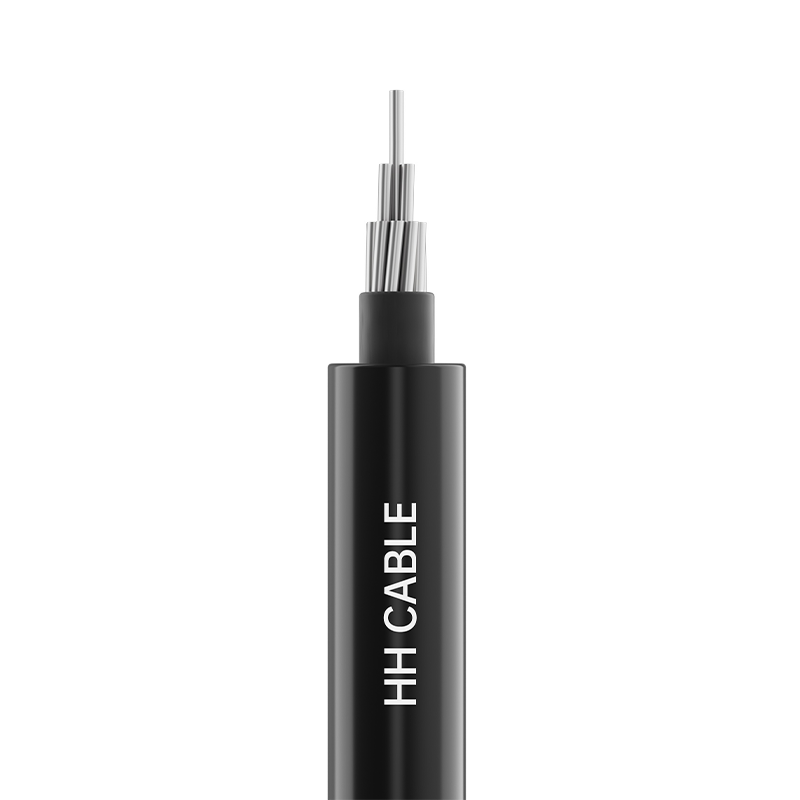
Selecting the correct overhead electrical cable for a transmission or distribution line requires balancing three interdependent variables: continuous current-carrying capacity, mechanical tensile strength, and long-term sag behavior under maximum operating temperature. For most medium and high-voltage applications, steel-reinforced aluminum conductor (ACSR) remains the default choice because the galvanized steel core carries approximately 55% to 65% of the total tension while the aluminum strands carry the current, a separation of functions that no homogeneous conductor can match at equivalent cost.
Content
- 1 Conductor types and material composition
- 2 Comparative performance of standard conductor types
- 3 Ampacity and thermal rating fundamentals
- 4 Sag-tension calculation and stringing practice
- 5 Aeolian vibration and conductor damping
- 6 Corona discharge and electromagnetic field management
- 7 Insulator selection and creepage distance coordination
- 8 Jointing, dead-ending, and hardware compatibility
Conductor types and material composition
Overhead electrical cables are classified by the materials and stranding configuration of the conductor. The three primary bare conductor families dominate the market, each suited to distinct span lengths and environmental conditions.
ACSR, or Aluminum Conductor Steel-Reinforced, consists of a concentric stranded steel core surrounded by one or more layers of hard-drawn 1350-H19 aluminum strands. The steel core, available in various strength grades, provides the tensile backbone, while the aluminum layers carry the current with a conductivity of 61.2% IACS (International Annealed Copper Standard). A typical ACSR "Drake" conductor, with a 26/7 stranding and an overall diameter of 28.14 mm, achieves a rated tensile strength of 140 kN and a continuous ampacity of approximately 907 amps at 75°C under moderate wind conditions.
AAAC, the all-aluminum alloy conductor, uses a homogeneous stranding of 6201-T81 aluminum alloy wires. This alloy incorporates magnesium and silicon to achieve a tensile strength roughly double that of 1350-H19 electrical conductor aluminum, eliminating the need for a steel core. AAAC conductors are specified where corrosion of the steel core is a concern, particularly in coastal or industrial environments with airborne chlorides or sulfur compounds. The absence of a magnetic steel core also eliminates hysteresis and eddy-current losses, reducing the AC resistance by approximately 3% to 5% compared to an equivalent-diameter ACSR under the same load current.
AAC, the all-aluminum conductor made entirely from 1350-H19 strands, offers the highest conductivity per unit weight but the lowest tensile strength. Its use is limited to short spans in urban distribution networks and bus-bar droppers within substations, where the span length rarely exceeds 50 meters and the conductor is not required to withstand high ice or wind loads.
Comparative performance of standard conductor types
| Conductor Type | Material | Tensile Strength (MPa) | Conductivity (% IACS) | Typical Span Limit (m) |
|---|---|---|---|---|
| ACSR | Aluminum 1350-H19 + Galvanized Steel | 1,200 – 1,550 | 61.2 | 300 – 1,200 |
| AAAC | 6201-T81 Aluminum Alloy | 295 – 330 | 52.5 – 53.0 | 100 – 500 |
| AAC | 1350-H19 Aluminum | 165 – 195 | 61.2 | 40 – 80 |
| ACSS | Annealed Aluminum + Steel | 1,200 – 1,550 | 63.0 | 300 – 1,200 |
Ampacity and thermal rating fundamentals
The ampacity of an overhead electrical cable is not a fixed number but a function of the heat balance between resistive losses (I²R heating), solar radiation absorbed by the conductor surface, convective cooling from wind, and radiative heat loss to the sky. The IEEE 738 standard defines the steady-state thermal equation that governs this balance. Under worst-case assumptions of full sun, low wind speed of 0.6 m/s, and an ambient temperature of 40°C, the ampacity of a given conductor may be 25% to 35% lower than the value published for moderate spring conditions.
Conductor operating temperature is the independent variable that controls sag. Standard ACSR conductors are rated for continuous operation at 75°C, 90°C, or 100°C, with higher temperatures permitted for emergency or short-term peak load conditions. Above 93°C, the aluminum strands begin to anneal, permanently reducing their tensile strength. High-temperature low-sag (HTLS) conductors such as ACSS, G(Z)TACSR, and ACCR use fully annealed aluminum or composite cores to operate continuously at 150°C to 210°C, roughly doubling the ampacity of a conventional ACSR line within the same right-of-way without requiring taller towers.
Sag-tension calculation and stringing practice
The relationship between conductor tension and sag is governed by the catenary equation, which for spans shorter than 300 meters simplifies to a parabolic approximation with acceptable error. The design process begins with the ruling span concept, a weighted average span length that represents the equivalent mechanical behavior of an entire tension section between dead-end structures. The initial unloaded tension at the lowest stringing temperature, typically -20°C or 0°F, must be set so that the conductor does not exceed 60% of its rated breaking strength under the most severe ice and wind load combination specified by the National Electrical Safety Code (NESC) for the geographic loading district.
Stringing is not simply pulling the conductor to a target tension and clamping it. The conductor must be tensioned to a sag value measured by sighting across the span with a transit or digital sagometer, with the conductor at a known uniform temperature. For a 300-meter span of ACSR Drake at 15°C with no wind or ice, the target sag is approximately 6.5 meters, corresponding to a horizontal tension of about 17 kN. After clipping in, the conductor relaxes through strand settling and metallurgical creep, losing approximately 10% to 15% of the initial tension over the first 1,000 hours of service. The stringing sag must anticipate this creep by targeting an over-tension of 10% to 12%, which then relaxes to the design final sag.
Aeolian vibration and conductor damping
When a steady laminar wind passes across an overhead cable at speeds between 1 and 7 m/s, it sheds alternating Kármán vortices that induce a cyclic lift force perpendicular to the wind direction. This aeolian vibration, with frequencies typically in the range of 3 to 150 Hz, forces the conductor to oscillate at or near a natural resonant frequency of one of its higher vibration modes. The resulting bending strain at the conductor suspension clamp, where the motion is fully restrained, exceeds the aluminum's fatigue endurance limit of approximately 57 MPa (8.3 ksi) within tens of millions of cycles, which accumulate in a matter of days during steady wind conditions.
Mitigation uses Stockbridge dampers, spiral vibration dampers (formally called dog-bone dampers or spiral-form damper elements), or spacer dampers on bundled conductors. A properly tuned Stockbridge damper has two resonant frequencies that bracket the dominant conductor frequency, absorbing vibratory energy through the internal friction of its messenger cable strands. Damper placement distance from the clamp is not arbitrary; it must be positioned at a point where the conductor's vibration antinode amplitude is sufficient to excite the damper. For a typical 132 kV line with ACSR Lynx conductor, the first damper is placed 0.8 to 1.2 meters from the suspension clamp mouth, with a second damper at 1.8 meters on spans exceeding 400 meters.
Corona discharge and electromagnetic field management
At transmission voltages of 230 kV and above, the electric field gradient at the conductor surface approaches the dielectric breakdown strength of air, approximately 30 kV/cm at sea level. When the surface gradient exceeds roughly 17 kV/cm under dry conditions, corona discharge initiates, producing audible noise, radio interference (RI) in the 0.5 to 1.6 MHz band, and power loss. The surface gradient is inversely proportional to the conductor radius; a single conductor per phase must have a diameter of at least 24 mm for 230 kV and 32 mm for 345 kV to keep the gradient below the corona threshold.
Bundled conductors address this by splitting the phase current among two, three, or four sub-conductors separated by rigid spacers at 30 to 45 cm intervals. A twin-bundle of 28 mm diameter conductors at 400 kV achieves an equivalent diameter of approximately 180 mm in terms of electric field distribution, reducing the surface gradient by a factor of roughly three compared to a single conductor of equivalent total cross-sectional area. The spacer spacing is chosen to optimize the balance between electric field uniformity and mechanical stability against sub-span oscillation, a phenomenon where the windward conductor shields the leeward one, creating an aerodynamic instability that drives elliptical whipping motions.
Insulator selection and creepage distance coordination
The overhead conductor is mechanically supported and electrically isolated by suspension or tension insulator strings. The insulator's creepage distance, the path length along the insulator surface from the energized end fitting to the grounded end, must be sufficient to prevent flashover under contaminated wet conditions. The specific creepage distance is defined in mm of creepage per kV of system phase-to-phase voltage. For light pollution areas, a specific creepage of 16 mm/kV is adequate; for heavy industrial or coastal salt spray, 31 mm/kV or more is specified, achieved by using longer strings or fog-type insulators with deeper skirts.
Composite polymeric insulators with silicone rubber sheds have largely displaced porcelain and glass cap-and-pin strings for new construction at 138 kV and below, and are gaining acceptance at EHV levels. The hydrophobic surface of silicone rubber causes water to bead rather than form a continuous conductive film, suppressing leakage current by a factor of 10 to 100 compared to a hydrophilic porcelain surface under identical contamination conditions. The primary failure mode of composite insulators is brittle fracture of the fiberglass core rod from acid attack or water ingress at a defective end-fitting seal, a mechanism that requires continuous monitoring of mechanical load and visual inspection of housing integrity.
Jointing, dead-ending, and hardware compatibility
The entire overhead line is only as reliable as its joints and terminations. Mid-span joints, required for conductor lengths exceeding standard reel capacities, must achieve a tensile strength of at least 95% of the conductor's rated breaking strength and an electrical resistance not exceeding 75% of the equivalent length of unjointed conductor. Compression-type full-tension joints, applied with a hexagonal die and a hydraulic press capable of 700 bar (10,000 psi), are the industry standard. The joint body is an aluminum sleeve that slides over the aluminum strands and a separate steel sleeve that grips the steel core. The two sleeves are swaged independently; the steel sleeve first, transferring the full rated tension across the core, followed by the aluminum sleeve, which carries the current around the steel joint.
Bimetallic galvanic corrosion occurs wherever aluminum conductor strands contact copper alloy hardware in the presence of an electrolyte. The aluminum, being anodic to copper, corrodes sacrificially. All compression connectors and clamp bodies for aluminum conductor must be made from aluminum alloy or be fully tin-plated to prevent direct copper-to-aluminum contact. At substation dead-end structures where aluminum overhead line transitions to copper bus-work, a bimetallic friction-welded transition lug isolates the two metals while providing a low-resistance current path rated for the full short-circuit current of the line.
PREV: Instrumentation Cable Types: Shielded, Armoured & Fire-Safe
NEXT:Railway Cable Troughing Guide: Types, Installation & Standards
NEXT:Railway Cable Troughing Guide: Types, Installation & Standards
Interested in cooperation or have questions?
Featured Products
Comprehensive Cable Solutions


Ready To Customise
Your Cable Products?
Your Cable Products?

Customized Cable Solutions, Bulk Wire Supplier in China. Relying on genuine core quality to build a renowned brand, striving to become a benchmark for advanced
cable standards.
Product Categories
Quick Links
Contact Us
-
Email: [email protected]

-
Mobile: +86-0510-87296815

-
Fax: +86-0510-87295158

-
No. 1, Fengyi Jinfeng Road, Guanlin Town, Yixing City, Jiangsu Province, China

Copyright © Wuxi Henghui Cable Co., Ltd. All Rights Reserved. Custom Cable Manufacturers Electrical Cables Factory
