


 English
 中文简体
中文简体 русский
Electric & Overhead Transmission Cable Guide
Electric & Overhead Transmission Cable Guide
Electric & Overhead Transmission Cable Guide
Electric & Overhead Transmission Cable Guide
Electric & Overhead Transmission Cable Guide
Electric & Overhead Transmission Cable Guide
Electric & Overhead Transmission Cable Guide
Electric & Overhead Transmission Cable Guide
Electric & Overhead Transmission Cable Guide
Electric & Overhead Transmission Cable Guide
Electric & Overhead Transmission Cable Guide
Electric & Overhead Transmission Cable Guide
Electric & Overhead Transmission Cable Guide
Electric & Overhead Transmission Cable Guide
Electric & Overhead Transmission Cable Guide
Electric & Overhead Transmission Cable Guide
Industry News
Product Category
NEW Category
Contact us
 +86-0510-87296815
Electric & Overhead Transmission Cable Guide
Content
- 1 Understanding Electric Transmission Cable in Modern Power Systems
- 2 Overhead Transmission Cable vs. Underground Cable: Core Trade-offs
- 3 Principal Conductor Types Used in Overhead Transmission Cable
- 4 Electrical Performance Parameters That Govern Conductor Selection
- 5 Mechanical Design Considerations for Overhead Transmission Lines
- 6 International Standards Governing Transmission Cable Specification
Understanding Electric Transmission Cable in Modern Power Systems
Electric transmission cable forms the physical backbone of every national and regional power grid. Its role is to carry bulk electrical energy at high voltage from generating stations — whether coal-fired, nuclear, hydroelectric, or renewable — across long distances to the substations that step voltage down for local distribution. The engineering decisions embedded in transmission cable selection have direct consequences for grid reliability, energy efficiency, capital expenditure, and the long-term operational costs borne by utilities and ratepayers. Understanding what differentiates one conductor type from another, and what factors govern selection for a specific project, is therefore foundational knowledge for power engineers, procurement specialists, and infrastructure planners.
Modern power transmission operates at voltage levels ranging from 66 kV on sub-transmission feeders to 1,100 kV on ultra-high-voltage direct current (UHVDC) interconnectors spanning thousands of kilometers. At every voltage level, the electric transmission cable must simultaneously minimize resistive losses, maintain mechanical integrity under wind, ice, and thermal loading, and remain serviceable for a design life that typically exceeds 40 years. These demands shape every aspect of conductor design, from the choice of conducting metal and cross-sectional geometry to the selection of core reinforcement materials and surface finish.
Overhead Transmission Cable vs. Underground Cable: Core Trade-offs
The most fundamental design choice in any transmission project is whether to route power overhead or underground. Overhead transmission cable dominates global high-voltage transmission infrastructure for well-established economic and technical reasons, but underground cable has expanded significantly in urban and environmentally sensitive corridors where aerial routing is impractical or politically unacceptable.
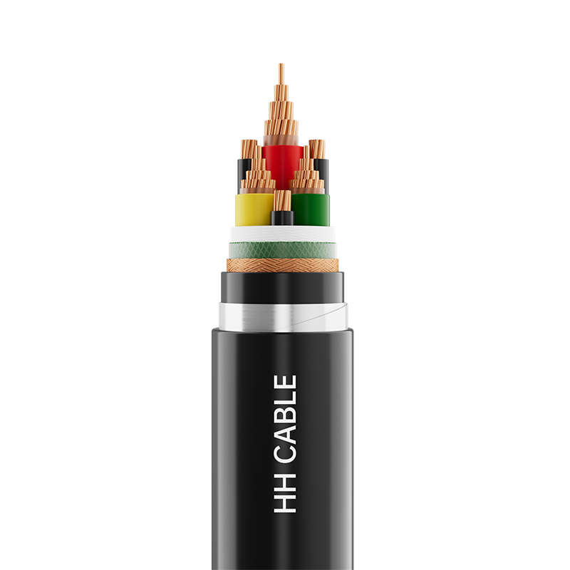
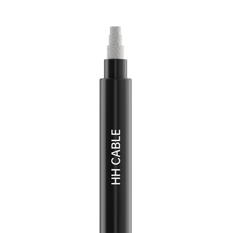
Overhead transmission cable is suspended between steel lattice towers or concrete poles using insulator strings that provide the necessary electrical clearance between the energized conductor and the grounded support structure. Because the surrounding air acts as the insulating medium, overhead conductors require no costly extruded insulation layer — the conductor is bare, exposed directly to the atmosphere. This eliminates a significant material cost, makes thermal dissipation straightforward, and allows visual inspection and maintenance without excavation. The capital cost of overhead transmission is typically three to ten times lower per kilometer than an equivalent underground cable circuit at transmission voltages, which is why overhead routing remains the default choice for rural and cross-country lines worldwide.
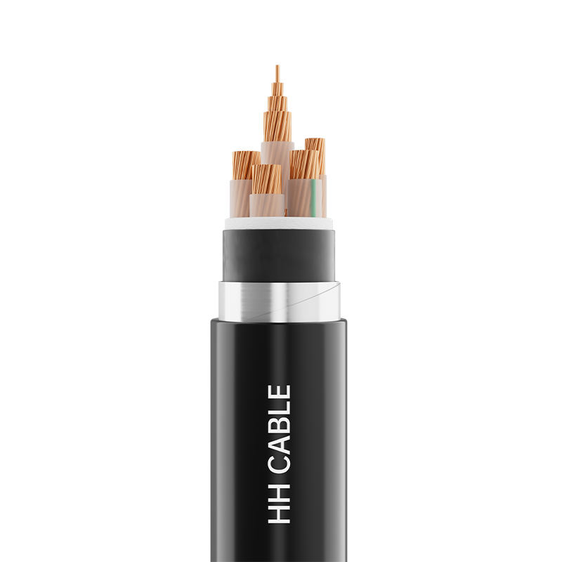
Underground electric transmission cable, by contrast, uses extruded cross-linked polyethylene (XLPE) insulation surrounded by metallic screens and protective sheaths to isolate the energized conductor from the surrounding soil. This construction eliminates weather-related outages caused by wind, ice, and lightning — the dominant causes of overhead line faults — but introduces different operational challenges including higher capacitive charging current over long distances, more complex fault location, and significantly greater repair time and cost when damage does occur. For transmission projects in dense urban environments, submarine crossings, or areas with strict landscape protection requirements, underground cable is the necessary choice despite its higher cost.
Principal Conductor Types Used in Overhead Transmission Cable
The conductor is the heart of any overhead transmission cable. A range of conductor constructions has been developed over the past century to optimize the balance between electrical conductivity, mechanical strength, weight, and cost for different span lengths, terrain types, and loading conditions. The following table summarizes the most widely deployed conductor families in high-voltage transmission applications:
| Conductor Type | Construction | Key Advantage | Typical Application |
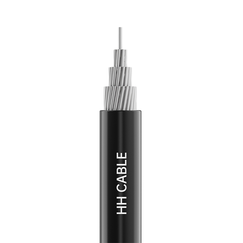
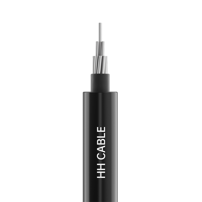
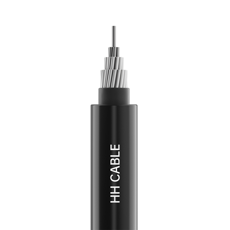
| ACSR | Aluminum strands over galvanized steel core | High strength-to-weight ratio, cost-effective | Rural HV lines, long spans |
| AAAC | All aluminum alloy strands | Superior corrosion resistance, lighter weight | Coastal and industrial environments |
| ACCC | Annealed aluminum over carbon fiber composite core | High-temperature operation, low sag | Grid reconductoring, constrained corridors |
| HTLS | Various high-temperature aluminum alloys with low-sag core | Double or triple ampacity vs. ACSR | Capacity uprating without new towers |
| OPGW | Optical fiber tubes within ground wire strands | Combined earth wire and communication fiber | Smart grid communication backbone |
ACSR (Aluminum Conductor Steel Reinforced) remains the single most widely installed overhead transmission cable conductor type globally, owing to its mature supply chain, well-understood mechanical behavior, and competitive cost. However, the growing pressure to maximize capacity on existing transmission corridors without constructing new tower lines has driven rapid adoption of HTLS (High-Temperature Low-Sag) conductors and composite-core designs such as ACCC, which can operate continuously at 150–210°C compared to ACSR's 75–90°C limit while maintaining lower sag profiles that preserve statutory ground clearance requirements.

Electrical Performance Parameters That Govern Conductor Selection
Selecting the right electric transmission cable for a specific project requires a quantitative evaluation of several interdependent electrical performance parameters. Each parameter interacts with the others, and optimizing for one — say, minimizing resistive losses — may require a trade-off against conductor weight, tower loading, or capital cost.
Ampacity and Thermal Rating
Ampacity — the maximum continuous current a conductor can carry without exceeding its design temperature — is the primary capacity parameter for any transmission line. It is determined by the balance between Joule heating (I²R losses) and heat dissipation to the environment through convection, radiation, and conduction. Standard ACSR conductors on a typical 400 kV double-circuit tower might carry 1,000–1,500 A per phase under normal rating conditions. Dynamic line rating (DLR) systems that use real-time weather data to calculate actual ampacity can unlock 10–30% additional capacity from existing overhead transmission cable infrastructure without any physical modification to the conductor.
Resistance and Line Losses
The DC resistance of a conductor is inversely proportional to its cross-sectional area and directly proportional to the resistivity of the conducting metal. For aluminum at 20°C, resistivity is approximately 2.82 × 10⁻⁸ Ω·m. A 400 mm² ACSR conductor on a 400 kV line carrying 1,000 A dissipates roughly 28 kW per kilometer as heat — losses that accumulate to tens of gigawatt-hours annually on a major interconnector. This is why selecting a larger conductor cross-section than the minimum required for thermal compliance is often economically justified when the present value of avoided energy losses over the line's 40-year life exceeds the incremental cost of the heavier conductor and stronger towers.
Corona and Radio Interference
At transmission voltages above 110 kV, the electric field intensity at the conductor surface can exceed the ionization threshold of air, producing corona discharge — a partial breakdown phenomenon that generates audible noise, radio frequency interference, and real power loss. Corona performance is governed primarily by the conductor surface gradient, which is reduced by increasing conductor diameter (through bundling or the use of expanded-core conductors) and by maintaining a smooth, clean surface finish. Modern overhead transmission cable designs for 220 kV and above almost universally employ bundled conductors — two, three, or four sub-conductors per phase — which simultaneously reduce surface gradient, lower inductance, and increase ampacity.
Mechanical Design Considerations for Overhead Transmission Lines
The mechanical design of an overhead transmission cable system is as demanding as its electrical design. Conductors must withstand the combined loading of their own weight, wind pressure on the projected area, and ice accretion on the conductor surface — all simultaneously in worst-case weather events. The design tension in the conductor, the sag at maximum operating temperature, and the clearance to ground, to other phases, and to the tower structure must all remain within specified limits across the full range of temperature and loading conditions anticipated over the line's lifetime.
- Everyday tension (EDT): Limiting the conductor tension at everyday conditions (typically 15°C, no wind, no ice) to 20–25% of rated tensile strength (RTS) controls fatigue at suspension clamps caused by Aeolian vibration — the sinusoidal oscillation induced by steady laminar wind flowing past the conductor.
- Maximum tension: Under the governing load case (typically maximum wind or maximum ice, depending on geographic location), conductor tension must not exceed 50–75% of RTS to maintain an adequate safety factor against tensile failure.
- Sag-tension calculation: The catenary curve formed by a conductor under gravity defines its sag at midspan. As conductor temperature increases under load, thermal elongation increases sag — reducing ground clearance. This is the fundamental constraint that limits the operating temperature of conventional ACSR and drives the adoption of low-sag HTLS conductors in thermally limited corridors.
- Vibration damping: Stockbridge dampers — tuned mass-spring devices clamped to the conductor near suspension points — absorb the energy of Aeolian vibration and prevent fatigue cracking of outer aluminum strands, which is the most common long-term mechanical failure mode in overhead transmission cable installations.
International Standards Governing Transmission Cable Specification
Procurement of electric transmission cable for utility and infrastructure projects requires compliance with recognized international or regional standards that specify conductor construction, material properties, dimensional tolerances, and test methods. The principal standards families are IEC (International Electrotechnical Commission), ASTM (American Society for Testing and Materials), and BS EN (British/European Standards), with national adaptations in major markets including China (GB/T), India (IS), and Australia (AS).
IEC 61089 and its successor IEC 62219 cover round wire concentric lay overhead electrical stranded conductors, specifying the mechanical and electrical properties of ACSR, AAAC, and related conductor types. IEC 62004 addresses high-temperature aluminum alloy wire for HTLS conductors. For underground transmission cable, IEC 60840 (voltages above 30 kV up to 150 kV) and IEC 62067 (above 150 kV) define the type test and routine test requirements for extruded insulation power cables. Compliance with these standards — demonstrated through accredited third-party type testing and factory quality audits — is a mandatory procurement requirement for most public utility transmission projects globally, ensuring that the electric transmission cable installed in critical infrastructure meets the performance and safety benchmarks validated by independent technical bodies.
Interested in cooperation or have questions?
Featured Products
Comprehensive Cable Solutions


Ready To Customise
Your Cable Products?
Your Cable Products?

Customized Cable Solutions, Bulk Wire Supplier in China. Relying on genuine core quality to build a renowned brand, striving to become a benchmark for advanced
cable standards.
Product Categories
Quick Links
Contact Us
-
Email: [email protected]

-
Mobile: +86-0510-87296815

-
Fax: +86-0510-87295158

-
No. 1, Fengyi Jinfeng Road, Guanlin Town, Yixing City, Jiangsu Province, China

Copyright © Wuxi Henghui Cable Co., Ltd. All Rights Reserved. Custom Cable Manufacturers Electrical Cables Factory
