


 English
 中文简体
中文简体 русский
Control Cables: Selection, Shielding & Installation Guide
Control Cables: Selection, Shielding & Installation Guide
Control Cables: Selection, Shielding & Installation Guide
Control Cables: Selection, Shielding & Installation Guide
Control Cables: Selection, Shielding & Installation Guide
Control Cables: Selection, Shielding & Installation Guide
Control Cables: Selection, Shielding & Installation Guide
Control Cables: Selection, Shielding & Installation Guide
Control Cables: Selection, Shielding & Installation Guide
Control Cables: Selection, Shielding & Installation Guide
Control Cables: Selection, Shielding & Installation Guide
Control Cables: Selection, Shielding & Installation Guide
Control Cables: Selection, Shielding & Installation Guide
Control Cables: Selection, Shielding & Installation Guide
Control Cables: Selection, Shielding & Installation Guide
Control Cables: Selection, Shielding & Installation Guide

Industry News
Product Category
NEW Category
Contact us
 +86-0510-87296815
Control Cables: Selection, Shielding & Installation Guide
Content
Understanding the Core Function of Control Cables
Control cables serve as the nervous system of industrial automation, transmitting low-energy signals that command, monitor, and regulate equipment. Unlike power cables that simply deliver electricity, these cables carry data pulses, analog signals, and digital instructions to relays, sensors, actuators, and programmable logic controllers. A failure in a control circuit can halt an entire production line, trigger safety hazards, or cause erratic machine behavior. The fundamental challenge lies in preserving signal integrity over distance while the cable is bombarded by electromagnetic interference from nearby motors, variable frequency drives, and high-voltage lines. Selecting the right control cable demands a precise understanding of voltage ratings, conductor configurations, insulation materials, and the specific environmental stressors the installation will face.
Decoding Conductor Configurations and Flexibility Classes
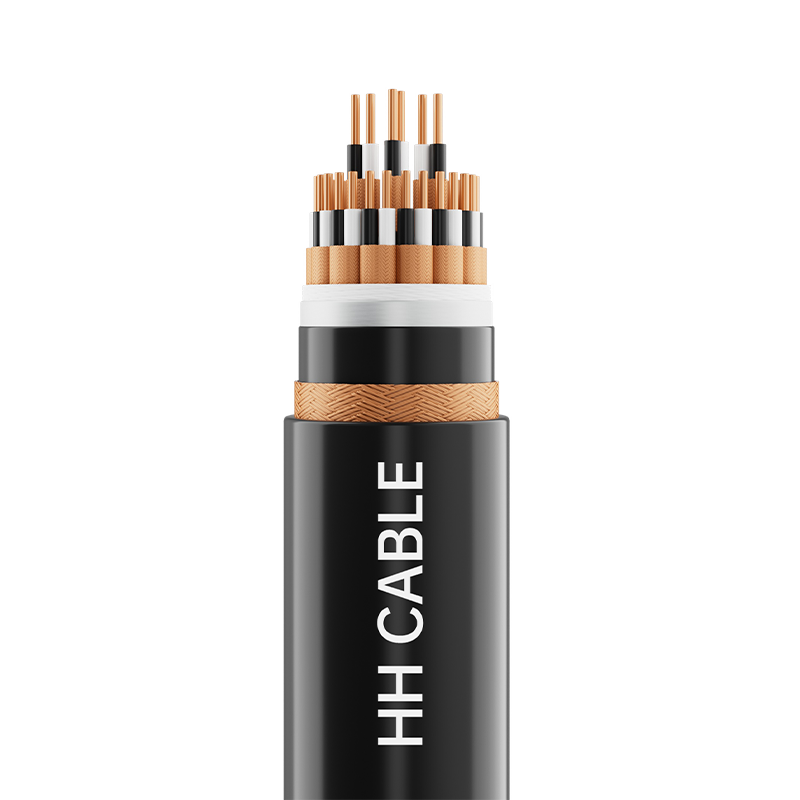
The physical construction of the copper conductor directly determines how a control cable performs under movement and in fixed installations. Conductors are classified by their stranding class, a detail often overlooked until a cable fails prematurely. The two primary configurations you will encounter are solid conductors and stranded conductors, with stranded further divided into fine-wire and extra-fine-wire classes.
Solid vs. Stranded Conductors
Solid conductors consist of a single copper wire. They offer the lowest cost and best electrical characteristics for fixed, undisturbed installations like building wiring. However, they are completely unsuitable for any application involving vibration or movement, as they will work-harden and snap. Stranded conductors, made of multiple thin wires twisted together, introduce flexibility. For control panels with static routing, a Class 2 stranded conductor provides a good balance of formability and durability. For applications involving continuous flexing, such as cable tracks, robotic arms, or vibrating machinery, a Class 5 or Class 6 extra-fine stranded conductor is non-negotiable. Specifying a Class 2 cable in a drag chain will cause copper fatigue and conductor breakage within a fraction of its expected service life.
Conductor Count and Numbering
Control cables frequently carry multiple circuits within a single jacket. A typical cable might contain 7, 12, 19, or even 37 conductors. Proper identification is critical. The standard color coding is black conductors with white printed numbers, with a yellow-green conductor reserved exclusively for protective earth grounding. When counting conductors, always include a spare or two beyond your immediate need. A 12-conductor cable with one green-yellow ground leaves 11 functional cores. Adding spare pairs during installation is significantly cheaper than pulling a new cable later for a retrofit or a failed conductor.
Shielding Strategies for Signal Integrity
Electromagnetic interference and radio frequency interference can superimpose false signals onto control circuits, causing sensors to misread and actuators to trigger falsely. Shielding is the primary defense mechanism, but the shield type must match the noise environment. Applying the wrong shielding strategy is as damaging as having no shield at all.
Foil Shields with Drain Wire
An aluminum-polyester foil tape, bonded to the inner jacket, provides 100% coverage. This physical barrier is exceptionally effective against high-frequency radio frequency interference. A tinned copper drain wire runs in contact with the metallic side of the foil, providing a means for easy termination. Foil shields are ideal for short runs in control panels with high-density electronic noise. The limitation is mechanical fragility; repeated flexing can crack the foil, creating gaps in coverage. For stationary instrument wiring, a foil shield offers premium protection at a moderate cost.
Braid Shields for Mechanical Strength
A braided shield, woven from fine tinned copper wires, typically achieves 70% to 95% coverage. The lower coverage compared to foil is offset by a dramatic increase in physical robustness and flexibility. Braid shields excel at absorbing low-frequency magnetic interference, the type generated by motors and transformers. They also provide a low-resistance path to ground, making them highly effective in applications with high fault currents. For any control cable that will experience vibration, repeated handling, or routing through machinery, a braid shield is superior. The termination of a braid shield requires more time than a drain wire, but the long-term reliability in dynamic environments justifies the effort.
Combination Foil and Braid Shields
In extreme electromagnetic environments, such as near large variable frequency drives or induction furnaces, a combination shield provides the ultimate protection. This construction layers a foil shield directly over the insulated conductors, followed by an overall braid shield. The foil blocks high-frequency radiated noise, while the braid handles low-frequency conducted noise and provides a robust termination point. Cables with combination shields are heavier, stiffer, and more expensive, but they are mandatory when you cannot physically separate control cables from high-power motor leads.
Insulation and Jacket Material Selection
The materials encasing the conductors determine temperature rating, chemical resistance, and fire behavior. Selecting the wrong jacket can lead to embrittlement and cracking within months. The following table compares common materials used in control cable manufacturing.
| Material | Temperature Range | Key Properties | Typical Use Case |
|---|---|---|---|
| PVC | -25°C to +90°C | Good oil resistance, flame retardant, low cost | General industrial wiring, machine tools |
| Polyurethane | -40°C to +80°C | Exceptional abrasion and cut resistance, halogen-free | Drag chains, robotics, harsh mechanical duty |
| Cross-linked Polyethylene | -40°C to +125°C | High thermal stability, excellent dielectric strength | Hot environments, engine compartments |
| Thermoplastic Elastomer | -50°C to +105°C | Flexible at very low temperatures, weld slag resistant | Outdoor installations, cold storage |
For installations in public buildings, tunnels, or enclosed transit systems, low-smoke zero-halogen materials are often required by fire safety codes. Standard PVC emits dense, toxic smoke and hydrochloric acid when burned. An LSZH jacket emits significantly less smoke and no corrosive gases, allowing personnel to evacuate safely and protecting sensitive electronic equipment from secondary corrosion damage.
Installation Guidelines and Segregation Principles
Even the finest control cable cannot perform if installed incorrectly. The physical placement of cables within a facility is the most powerful tool for controlling electromagnetic interference. The core principle is distance and perpendicular crossing.
Physical Separation Categories
Control cables must be physically separated from power cables according to voltage level and current. As a rule, maintain a minimum distance of 200 millimeters between control cables and low-voltage power lines under 1000V. For medium-voltage motor cables, this distance increases to 500 millimeters. When control cables and power cables must cross, they should do so at a strict 90-degree angle. Parallel routing of control and power cables over long distances is a textbook error that induces a coupling voltage, corrupting analog 4-20 mA signals and causing nuisance trips. Run control circuits in dedicated steel cable trays with a grounded divider if they must share a tray route with power conductors.
Grounding the Shield Correctly
Improper shield grounding creates ground loops that inject hum directly into the signal path. The shield must be terminated at one end only for low-frequency analog signals, typically at the control panel end. The opposite end is cut flush and insulated with heat-shrink tubing. Grounding both ends of a shield creates a potential difference if the ground planes at the field device and the panel are at slightly different voltages, causing current to flow on the shield itself. This current induces noise onto the very conductors the shield is meant to protect. For high-frequency digital communication cables, however, such as those using Profibus or CANbus protocols, grounding the shield at both ends is actively recommended to create a Faraday cage, provided the installation includes an equipotential bonding conductor to equalize ground potentials.
Specifying Cables for Dynamic Applications
Control cables installed in moving machinery, cable carriers, or robotic arms demand an entirely different mechanical specification than those in static trays. The copper conductor must be fine-stranded, and the lay length of the stranding must be precisely short to distribute bending stresses evenly. The cable jacket must be a wear-resistant material like polyurethane. During installation in a drag chain, the cable must never be twisted. The fill ratio inside the chain should prevent cables from rubbing against each other or the chain walls. A horizontal separation bar between cables is mandatory in longer travel lengths. Every control cable in dynamic service will eventually fail due to copper fatigue; a proper installation maximizes the cycle life, and service loops at the termination points prevent tension from pulling directly on the connectors.
PREV:Railway Cable Troughing Guide: Types, Installation & Standards
NEXT:XLPE Insulated Control Cable 450/750V: Specs, Types & Installation Guide
NEXT:XLPE Insulated Control Cable 450/750V: Specs, Types & Installation Guide
Interested in cooperation or have questions?
Featured Products
Comprehensive Cable Solutions


Ready To Customise
Your Cable Products?
Your Cable Products?

Customized Cable Solutions, Bulk Wire Supplier in China. Relying on genuine core quality to build a renowned brand, striving to become a benchmark for advanced
cable standards.
Product Categories
Quick Links
Contact Us
-
Email: [email protected]

-
Mobile: +86-0510-87296815

-
Fax: +86-0510-87295158

-
No. 1, Fengyi Jinfeng Road, Guanlin Town, Yixing City, Jiangsu Province, China

Copyright © Wuxi Henghui Cable Co., Ltd. All Rights Reserved. Custom Cable Manufacturers Electrical Cables Factory
