


 English
 中文简体
中文简体 русский
Cable Crimps for Control Cables: Selection, Installation & Quality Standards
Cable Crimps for Control Cables: Selection, Installation & Quality Standards
Cable Crimps for Control Cables: Selection, Installation & Quality Standards
Cable Crimps for Control Cables: Selection, Installation & Quality Standards
Cable Crimps for Control Cables: Selection, Installation & Quality Standards
Cable Crimps for Control Cables: Selection, Installation & Quality Standards
Cable Crimps for Control Cables: Selection, Installation & Quality Standards
Cable Crimps for Control Cables: Selection, Installation & Quality Standards
Cable Crimps for Control Cables: Selection, Installation & Quality Standards
Cable Crimps for Control Cables: Selection, Installation & Quality Standards
Cable Crimps for Control Cables: Selection, Installation & Quality Standards
Cable Crimps for Control Cables: Selection, Installation & Quality Standards
Cable Crimps for Control Cables: Selection, Installation & Quality Standards
Cable Crimps for Control Cables: Selection, Installation & Quality Standards
Cable Crimps for Control Cables: Selection, Installation & Quality Standards
Cable Crimps for Control Cables: Selection, Installation & Quality Standards
Industry News
Home / News / Industry News / Cable Crimps for Control Cables: Selection, Installation & Quality Standards
Product Category
NEW Category
Contact us
 +86-0510-87296815
Cable Crimps for Control Cables: Selection, Installation & Quality Standards
Content
What Are Control Cables and Why Crimping Matters
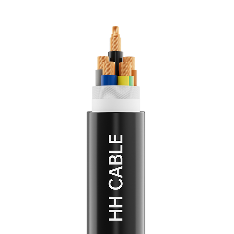
A faulty termination can bring an entire production line to a halt — not because the cable itself failed, but because of how it was connected. Control cables are the backbone of industrial signal transmission, carrying precise commands between sensors, actuators, PLCs, and control panels at voltages typically ranging from 24V to 600V. Unlike power cables that prioritize energy throughput, control cables are engineered for signal fidelity: their multi-core structure keeps each conductor isolated, minimizing interference and ensuring commands arrive intact.
Cable crimps — the mechanical connection points where conductors meet terminals — are where that signal fidelity either holds or breaks down. A properly crimped connection compresses the terminal barrel around the conductor strands to form a gas-tight joint, blocking moisture and oxygen that would otherwise cause corrosion and rising resistance. Done right, crimping outperforms soldering in vibration resistance and long-term reliability. Done wrong, it introduces the exact failure mode that industrial control cables and instrumentation cables are designed to prevent.
This guide walks through the full picture: control cable types and their termination requirements, crimp selection criteria, installation procedure, applicable standards, and the mistakes most likely to compromise a connection.

Types of Control Cables and Their Crimping Requirements
Control cables are not a monolithic category. Construction varies significantly depending on the environment, signal type, and degree of mechanical stress — and those differences translate directly into how the cable must be crimped.
PVC-insulated multicore cables are the workhorses of standard factory environments. Their conductors are typically Class 2 stranded copper, and they accept most standard uninsulated or insulated ferrule-type crimps. The relatively stiff construction makes consistent conductor alignment straightforward during termination.
Shielded variants — commonly designated CY (braided copper screen) or SY (steel wire armoured with copper screen) — add an extra layer of complexity. The shield must be properly grounded, and the crimp sequence must account for drain wire termination to avoid compromising EMI protection. These cables are standard in environments with high electromagnetic noise, such as motor control cabinets and variable frequency drive panels.
XLPE-insulated control cables handle higher operating temperatures and offer superior resistance to chemical exposure. Their insulation is harder, which affects stripping — over-aggressive stripping can nick conductors and create stress points right at the crimp entry. Fine-stranded Class 5 or Class 6 conductors, common in flexible control cables used in robotics and cable track applications, require ferrule crimps specifically rated for fine-strand wire; standard crimps designed for Class 2 stranded wire will not contain the strands adequately. For demanding dynamic routing environments, see our range of rail and transit cables for demanding environments.
| Cable Type | Conductor Class | Recommended Crimp Type | Key Consideration |
|---|---|---|---|
| PVC Multicore | Class 2 | Uninsulated / insulated ferrule | Standard tooling; verify AWG match |
| CY / SY Shielded | Class 2 / Class 5 | Ferrule + shield drain terminal | Ground shield separately; maintain EMI integrity |
| XLPE Insulated | Class 2 | Uninsulated compression terminal | Careful stripping to avoid nicking |
| Flexible / Fine-Strand | Class 5 / Class 6 | End-sleeve ferrule (bootlace type) | Fine-strand rated ferrule mandatory |
How to Choose the Right Cable Crimps
Selecting a crimp terminal is not a matter of grabbing whatever fits — it is a three-variable matching problem: conductor cross-section, terminal material, and terminal type. Get any one wrong and the connection will either be mechanically weak, electrically resistive, or both.
Conductor cross-section matching is the non-negotiable starting point. Terminal manufacturers specify the acceptable wire gauge range for each product, often in both mm² and AWG. A conductor that is too small will float inside the barrel and make intermittent contact. One that is too large will not compress correctly, leaving gaps between strands and the terminal wall. Always verify against the actual stripped conductor diameter, not just the cable's nominal specification — insulation thickness and stranding class can affect the final stripped bundle size.
Terminal material determines corrosion behavior over time. Tinned copper terminals are the standard choice for copper conductors in most industrial control applications; the tin plating prevents galvanic corrosion at the copper-to-copper interface while maintaining excellent conductivity. In high-humidity or marine-adjacent environments, silver-plated variants offer additional protection. Avoid mixing dissimilar metals — aluminum conductors crimped into copper terminals accelerate galvanic corrosion and are a known failure point.
Insulated vs. uninsulated ferrules comes down to the termination point. Insulated (color-coded) ferrules are preferred for control cabinet wiring because the sleeve protects the conductor entry from abrasion and makes the installation visually inspectable by AWG size. Uninsulated ferrules are used where space is tight or where the terminal block provides its own insulation. For bare wire entry into screw terminals, a bootlace ferrule is strongly recommended over unprotected fine-strand wire, which tends to splay under clamping torque and lose strands over time.
Step-by-Step Guide to Crimping Control Cables
Consistent crimp quality depends on process discipline, not just tool quality. The following sequence applies to ferrule termination of control cable conductors in industrial panel wiring — the most common scenario in automation and instrumentation installations.
- Gather correct tools and materials. Confirm you have a ratchet-type crimping tool matched to the ferrule series in use. Non-ratchet tools allow the operator to release before full compression is reached — a leading cause of under-crimped joints. Verify the die cavity size matches the ferrule and conductor gauge.
- Strip the conductor precisely. Use a calibrated wire stripper set to the correct insulation OD. Strip length should match the ferrule barrel depth — typically 8–12 mm for standard control wire ferrules. Under-stripping leaves insulation inside the barrel; over-stripping exposes bare conductor beyond the crimp, creating a potential short circuit in close-pitch terminal blocks.
- Inspect the stripped end. Check that all strands are intact and aligned. Any nicked or cut strands reduce the effective cross-section and introduce a stress concentration point. Discard and re-strip if strands are damaged.
- Insert the conductor fully into the ferrule. The stripped conductor should seat completely into the barrel with no strands protruding from the crimp end. For fine-strand conductors, twist the bundle lightly before insertion to keep strands organized.
- Crimp to full compression. Insert the loaded ferrule into the correct die cavity and compress until the ratchet releases. Do not attempt to interrupt the stroke. Full compression creates the gas-tight joint that prevents oxidation at the conductor interface.
- Inspect and test the crimp. Visually confirm the ferrule is not cracked, deformed asymmetrically, or cut through by the die. Perform a pull test by hand — the conductor should not slide within the ferrule under firm manual tension. For critical circuits, use a calibrated pull-force gauge to verify against the specification for that ferrule size.
Quality Standards for Crimp Connections on Control Cables
Crimp quality is not self-certifying — it requires reference to established standards that define acceptable geometry, pull-force minimums, and inspection protocols. Three frameworks govern the majority of industrial control cable crimping work globally.
IEC 61238-1 is the primary international standard covering compression and mechanical connectors for power cables, including cable lugs and terminals. It defines type-testing procedures, required conductor sizes, temperature cycling requirements, and maximum resistance values for a qualified connection. Specifying IEC 61238-1 compliant terminals gives procurement teams a verified baseline for electrical and mechanical performance across suppliers.
IPC/WHMA-A-620 is the dominant quality standard for cable and wire harness assemblies in electronics and industrial manufacturing. It establishes acceptance criteria for crimp height, conductor strand count, insulation damage limits, and visual inspection requirements across three workmanship classes. Class 2 (Dedicated Service) applies to most industrial control applications; Class 3 (High Reliability) applies to safety-critical or aerospace-adjacent systems.
UL 486A-B covers wire connectors and soldering lugs for use with copper conductors. It specifies pull-strength values, temperature ratings, and resistance requirements tied to conductor gauge. UL listing on crimp terminals provides assurance that the product has been independently tested for the rated application, which is often a requirement for control panels destined for North American markets.
Beyond terminal-level standards, the crimping tool itself must be calibrated. Uncalibrated tools are one of the leading root causes of field crimp failures — a worn die that was once correctly sized will produce under-compressed joints that pass visual inspection but fail under thermal cycling. Calibration cycles for crimping tools should be defined in the facility's quality management system. For manufacturers supplying industrial cable solutions for automation, tool traceability is a standard audit requirement under ISO 9001.
Common Crimping Mistakes and How to Avoid Them
Most crimp failures in the field trace back to a short list of process errors. Understanding them is the most direct path to eliminating them.
Wrong ferrule size. Using a 1.5 mm² ferrule on a 2.5 mm² conductor (or vice versa) is the single most common error in panel wiring. Color-coding helps but is not foolproof — different manufacturers use different color conventions. Always verify against the ferrule's printed AWG or mm² marking, not just the sleeve color.
Mismatched tool and terminal series. Crimp tools and terminals are designed as matched systems. A die from one manufacturer applied to a terminal from another may produce a mechanically sound-looking crimp that fails pull testing. This is especially problematic with proprietary ferrule geometries. Use the tool specified or recommended by the terminal manufacturer.
Partial compression. With non-ratchet tools, operators sometimes release pressure partway through the stroke — particularly when the tool feels stiff or when working in a tight space. The result is an under-compressed joint where conductor strands are held but not consolidated. The fix is simple: use a ratchet tool and never interrupt the stroke.
Stripping damage. Wire strippers set for the wrong insulation diameter nick conductors rather than cleanly releasing the insulation. In control cables, where individual conductors may be 0.5–1.5 mm², even one or two cut strands represent a meaningful loss of cross-section. Calibrate strippers to the cable being worked, and inspect every stripped end before insertion.
Skipping the pull test. Visual inspection catches obvious defects — cracked barrels, exposed strands, asymmetric compression — but it cannot confirm that the crimp force was sufficient. A brief manual pull test on every termination, and a measured pull test on a sample basis for critical circuits, is the minimum acceptable quality gate. Skipping it trades seconds at the workbench for hours of fault-finding in the field.
PREV:Overhead Insulated Cable and XLPE Insulated Cable: A Complete Guide for Modern Power Distribution
NEXT:Termite Resistant Cable: How It Works, Key Types & Selection Guide
NEXT:Termite Resistant Cable: How It Works, Key Types & Selection Guide
Interested in cooperation or have questions?
Featured Products
Comprehensive Cable Solutions


Ready To Customise
Your Cable Products?
Your Cable Products?

Customized Cable Solutions, Bulk Wire Supplier in China. Relying on genuine core quality to build a renowned brand, striving to become a benchmark for advanced
cable standards.
Product Categories
Quick Links
Contact Us
-
Email: [email protected]

-
Mobile: +86-0510-87296815

-
Fax: +86-0510-87295158

-
No. 1, Fengyi Jinfeng Road, Guanlin Town, Yixing City, Jiangsu Province, China

Copyright © Wuxi Henghui Cable Co., Ltd. All Rights Reserved. Custom Cable Manufacturers Electrical Cables Factory
