


 English
 中文简体
中文简体 русский
AWG Cable Meaning: How the American Wire Gauge Standard Affects Your Cable Choice
AWG Cable Meaning: How the American Wire Gauge Standard Affects Your Cable Choice
AWG Cable Meaning: How the American Wire Gauge Standard Affects Your Cable Choice
AWG Cable Meaning: How the American Wire Gauge Standard Affects Your Cable Choice
AWG Cable Meaning: How the American Wire Gauge Standard Affects Your Cable Choice
AWG Cable Meaning: How the American Wire Gauge Standard Affects Your Cable Choice
AWG Cable Meaning: How the American Wire Gauge Standard Affects Your Cable Choice
AWG Cable Meaning: How the American Wire Gauge Standard Affects Your Cable Choice
AWG Cable Meaning: How the American Wire Gauge Standard Affects Your Cable Choice
AWG Cable Meaning: How the American Wire Gauge Standard Affects Your Cable Choice
AWG Cable Meaning: How the American Wire Gauge Standard Affects Your Cable Choice
AWG Cable Meaning: How the American Wire Gauge Standard Affects Your Cable Choice
AWG Cable Meaning: How the American Wire Gauge Standard Affects Your Cable Choice
AWG Cable Meaning: How the American Wire Gauge Standard Affects Your Cable Choice
AWG Cable Meaning: How the American Wire Gauge Standard Affects Your Cable Choice
AWG Cable Meaning: How the American Wire Gauge Standard Affects Your Cable Choice

Industry News
Home / News / Industry News / AWG Cable Meaning: How the American Wire Gauge Standard Affects Your Cable Choice
Product Category
NEW Category
Contact us
 +86-0510-87296815
AWG Cable Meaning: How the American Wire Gauge Standard Affects Your Cable Choice
AWG, meaning American Wire Gauge, is the standard used in North America to describe the diameter of round, solid, nonferrous electrical conductors. The scale is logarithmic: each step down in gauge number corresponds to a fixed percentage increase in cross-sectional area. This is why a 10 AWG conductor carries substantially more current than a 14 AWG conductor, and why cable selection begins with reading the AWG number on a datasheet.
Core takeaway: A lower AWG number means a thicker conductor, higher current capacity, lower resistance, and lower voltage drop. A higher AWG number means a thinner conductor, less copper, and less current-carrying ability. For power circuits, the gauge you choose directly determines how much current the cable can safely handle without overheating.
Content
How AWG Numbers Work
The AWG scale is logarithmic, with 39 steps between 0000 (4/0) and 36 AWG. A 10 AWG wire has roughly 2.59 times the cross-sectional area of a 14 AWG wire, and a 6 AWG wire has roughly 2.26 times the area of a 10 AWG wire. The diameter doubles every six gauge sizes, and the area doubles every three gauge sizes. This rule allows engineers to quickly estimate whether a given cable can meet a current requirement without consulting a full table every time.
Diameter Trend
As the AWG number increases, the conductor diameter decreases. A 24 AWG wire is noticeably thinner than a 12 AWG wire, even though both can look similar at a glance.
Current Capacity
Thicker conductors carry more current before heating to the insulation temperature limit. This is why AWG is typically the first value an engineer checks when designing a branch circuit.
Resistance
Lower AWG wires have lower DC resistance. A 12 AWG copper conductor has about 0.00162 ohm per meter, while a 24 AWG conductor has about 0.0842 ohm per meter.
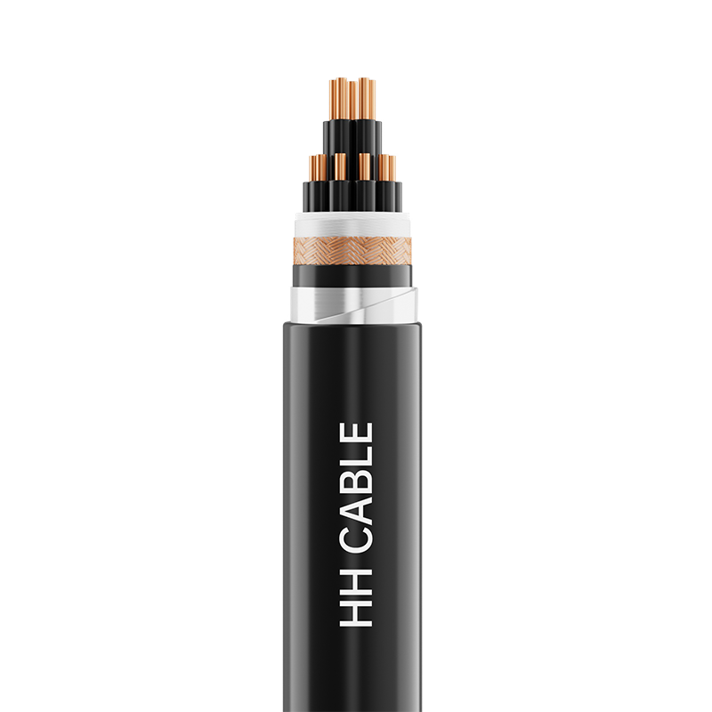 450-750V XLPE Insulated Control Cable for Industrial ApplicationsThis control cable is designed for 450-750V systems, offering reliable performance in industrial environments. Its XLPE insulation provides good thermal and electrical properties, making it suitable for power distribution and control circuits where consistent conductivity is essential.View Product →
AWG to Metric Conversion: Key Sizes
Cross-referencing AWG with metric conductor sizes helps when sourcing cables for European or Chinese standard systems. The table below shows typical conversion values for frequently used AWG sizes.
AWG
Diameter (mm)
Area (mm²)
Typical Ampacity (A)
14
1.63
2.08
15
12
2.05
3.31
20
10
2.59
5.26
30
8
3.26
8.37
40
6
4.12
13.3
55
4
5.19
21.2
70
2
6.54
33.6
95
Typical ampacity values are based on 60°C rated insulation in free air; actual values depend on installation environment and conductor material.
Voltage Drop and Copper Loss
Voltage drop is often the hidden constraint in long cable runs. For a 30A branch circuit running 50 meters, a 10 AWG copper conductor drops about 1.2% of the source voltage, while a 14 AWG conductor drops about 3.5%. In industrial settings, exceeding 3% can cause motor torque loss, relay chatter, and equipment shutdowns.
14 AWG: 3.5%
12 AWG: 2.7%
10 AWG: 1.2%
8 AWG: 0.8%
For signal and instrumentation circuits, the same electrical principle applies in a different way: smaller conductors add more loop resistance, which reduces the accuracy of the transmitted signal. Choosing a cable with the right copper cross-section for the intended signal range is essential for stable data acquisition.
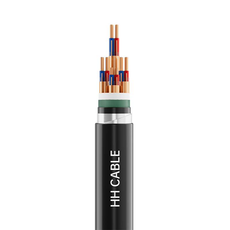 300-500V Computer and Instrument Cable for Signal AccuracySpecifically engineered for computer and instrumentation circuits, this cable ensures minimal signal loss by offering precise conductor sizes. With various insulation options, it supports accurate data transmission in control and monitoring systems.View Product →
Where AWG Sizes Appear in Industry
Different industries favor different gauge ranges. Building wiring commonly uses 12 AWG and 14 AWG for branch circuits. Automotive electrical systems rely on 18 AWG to 12 AWG for harness wiring. Industrial control panels often use 16 AWG to 10 AWG for motor circuits, while power distribution systems use 2 AWG and larger for feeders. Understanding the dominant gauge range in your industry simplifies procurement planning.
Building wiring: 35%
Industrial control: 30%
Automotive: 20%
Power distribution: 15%
Photovoltaic systems have their own voltage-drop constraint. Because DC current flows from the array to the inverter over long distances, undersized cables can significantly reduce system output. Our EN standard solar photovoltaic cables are sized to help you comply with European installation codes and keep DC losses within acceptable ranges.
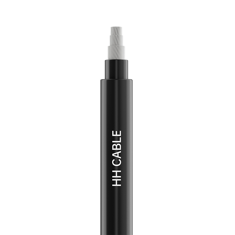 EN Standard Solar Photovoltaic Cable for Efficient DC PowerCompliant with European standards, this solar photovoltaic cable features tinned copper conductors and low-smoke halogen-free materials. It helps minimize DC voltage drop, ensuring optimal power output from solar arrays to inverters.View Product →
A Practical AWG Selection Guide
Selecting the right AWG size involves more than copying a number from a chart. Use these four steps for field-ready decisions.
Step 1: Determine Continuous Load
Multiply the motor or appliance current by 1.25 for continuous loads. This accounts for heat buildup over time and keeps the conductor below its thermal limit.
Step 2: Correct for Ambient Temperature
If the cable is routed through a high-temperature area, derate the ampacity using the correction factors listed in the installation standard. This is especially relevant for industrial enclosures.
Step 3: Check Voltage Drop
For runs longer than 50 meters, use the voltage-drop formula. If the calculated drop is above 3%, move up one AWG size or reduce the run length.
Step 4: Consider Special Environments
If the cable will be exposed to vibration, hazardous gases, or frequent bending, choose a stranded, shielded, or special-insulation cable that meets the area classification.
Maintenance and Compliance Considerations
After installation, the AWG rating on a cable helps you plan maintenance schedules. A common practice is to measure ampacity and voltage drop at the same point in the circuit where the cable exits the panel. Keeping the voltage drop within 3% typically protects insulation and downstream equipment. In hazardous industrial environments, follow the area classification and select cables approved for that zone. Our guidance on instrumentation cables in hazardous zones shows how a certified design reduces the risk of premature insulation failure and simplifies compliance audits.
PREV:Copper vs Aluminum Wire: Conductivity, Cost, and How to Choose for Your Project
NEXT:Power Cable Manufacturing: Process, Quality Control, and Selection Guide for Buyers
NEXT:Power Cable Manufacturing: Process, Quality Control, and Selection Guide for Buyers
Interested in cooperation or have questions?
Featured Products
Comprehensive Cable Solutions


Ready To Customise
Your Cable Products?
Your Cable Products?

Customized Cable Solutions, Bulk Wire Supplier in China. Relying on genuine core quality to build a renowned brand, striving to become a benchmark for advanced
cable standards.
Product Categories
Quick Links
Contact Us
-
Email: [email protected]

-
Mobile: +86-0510-87296815

-
Fax: +86-0510-87295158

-
No. 1, Fengyi Jinfeng Road, Guanlin Town, Yixing City, Jiangsu Province, China

Copyright © Wuxi Henghui Cable Co., Ltd. All Rights Reserved. Custom Cable Manufacturers Electrical Cables Factory
