


 English
 中文简体
中文简体 русский
HV Cable Guide: Selecting, Testing and Installing 66-110 kV XLPE Cables
HV Cable Guide: Selecting, Testing and Installing 66-110 kV XLPE Cables
HV Cable Guide: Selecting, Testing and Installing 66-110 kV XLPE Cables
HV Cable Guide: Selecting, Testing and Installing 66-110 kV XLPE Cables
HV Cable Guide: Selecting, Testing and Installing 66-110 kV XLPE Cables
HV Cable Guide: Selecting, Testing and Installing 66-110 kV XLPE Cables
HV Cable Guide: Selecting, Testing and Installing 66-110 kV XLPE Cables
HV Cable Guide: Selecting, Testing and Installing 66-110 kV XLPE Cables
HV Cable Guide: Selecting, Testing and Installing 66-110 kV XLPE Cables
HV Cable Guide: Selecting, Testing and Installing 66-110 kV XLPE Cables
HV Cable Guide: Selecting, Testing and Installing 66-110 kV XLPE Cables
HV Cable Guide: Selecting, Testing and Installing 66-110 kV XLPE Cables
HV Cable Guide: Selecting, Testing and Installing 66-110 kV XLPE Cables
HV Cable Guide: Selecting, Testing and Installing 66-110 kV XLPE Cables
HV Cable Guide: Selecting, Testing and Installing 66-110 kV XLPE Cables
HV Cable Guide: Selecting, Testing and Installing 66-110 kV XLPE Cables

Industry News
Home / News / Industry News / HV Cable Guide: Selecting, Testing and Installing 66-110 kV XLPE Cables
Product Category
NEW Category
Contact us
 +86-0510-87296815
HV Cable Guide: Selecting, Testing and Installing 66-110 kV XLPE Cables
Two 110 kV feeders in the same trench, carrying the same load through the same 630 mm² copper conductor. One is still running base load after twenty-five years. The other was excavated at year seven, after two joint failures and partial discharge readings that never quite cleared the acceptance limit. Nobody blamed the copper. The difference came down to three things: the extruded semiconductor layers, the moisture barrier wrapped over the insulation screen, and whether the joints were assembled in a controlled factory bay or in a damp, dusty pit.
Conclusion first: above 66 kV, an HV cable should be bought on insulation system and test evidence, not on price per metre. Four numbers decide the outcome — the voltage designation U0/U (Um), the extruded wall thickness, the partial discharge limit and the metallic screen type. Fix all four in the tender document before quotations are opened, because they cannot be retrofitted into a cable that has already been extruded.
The sections below walk through the design logic, the acceptance numbers, where failures actually originate, and how a selection sequence can be built so it survives both a technical review and a warranty claim.
Content
What Actually Makes a Cable High Voltage
Voltage class is a design statement, not a marketing label. An HV cable is written as U0/U (Um) — for example 64/110 (123) kV — where U0 is the phase-to-earth voltage the insulation is built around, U is the phase-to-phase rating, and Um is the highest system voltage the cable must tolerate continuously. Confusing U0 with U is one of the most common tender errors, and it silently strips a full insulation class out of the design.
Where the standards divide
IEC 60840 covers extruded-insulation power cables from 30 kV (Um = 36 kV) up to 150 kV (Um = 170 kV). IEC 62067 takes over from 150 kV to 500 kV. In practice, 66 kV, 110 kV and 132 kV class cables live inside IEC 60840, working alongside national equivalents such as GB/T 22078 in China and AEIC CS9 in North America. When a specification quotes only "HV cable" without naming the standard edition, the acceptance criteria are undefined — and so is the test plan.
Insulation: XLPE took the high ground
Cross-linked polyethylene replaced mass-impregnated paper and oil-filled designs for three practical reasons: a 90 °C continuous conductor temperature, a 250 °C limit for short-circuit duty of up to five seconds, and dielectric losses low enough to matter only on very long runs. XLPE also tolerates pre-moulded joints, which removes a large share of field risk. Its weakness is sensitivity. A protrusion or an irregularity of a few tens of microns at the semiconductor interface can initiate a discharge that grows quietly for years.
Conductor
Compacted stranded copper or aluminium. Above roughly 1600 mm², Milliken segmental conductors are used to keep skin and proximity effects under control and to hold down the outer diameter.
Semiconductor screens
Extruded inner and outer semiconductive layers, typically 1.0 to 1.5 mm thick, bonded to the insulation. Protrusion and surface roughness are held well under 0.2 mm, because this interface sets the partial discharge behaviour.
Metallic screen
Lead for longitudinal water blocking, corrugated aluminium for lower weight and better mechanical strength, or copper wires for cross-bonded long runs. The choice drives short-circuit capability and sheath loss.
Oversheath
Extruded HDPE or PVC, usually with a graphite coating so the outer layer can carry the commissioning test and support fault location. Direct-buried routes often add a protective layer against mechanical damage.
Geometry matters as much as materials. A 64/110 kV single-core cable at 630 mm² has an outer diameter near 95 mm, and the minimum bending radius is typically 15 to 20 times that diameter. Pulling tension is usually capped around 50 N/mm² of copper conductor cross-section, and closer to 30 N/mm² for aluminium. Route surveys that ignore these figures produce the most expensive kind of rework, because the cable is damaged long before it is energised. When we built our own 110 kV class XLPE power cable capability, the online eccentricity and diameter monitoring was specified for exactly this reason: eccentricity that drifts during extrusion is invisible once the drum is shipped.
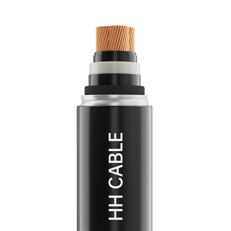 66-110kV Cross-Linked Polyethylene Insulated Power CableProduct Name: 66-110kV cross-linked polyethylene insulated power cableView Product →
Reading the Numbers by Voltage Class
The fastest way to spot an under-specified HV cable quotation is to compare it against the class it claims to meet. The table below lists the figures a technical reviewer should expect to see documented.
Figures are typical values for XLPE-insulated single-core cable at common conductor sizes; always confirm against the current edition of the governing standard and the project specification.
Where HV Cable Failures Actually Come From
Operator failure reports keep pointing at the same pattern. The cable drum is rarely the weakest link; the interface between the cable and everything around it usually is. The distribution below is a useful planning assumption when allocating budget between material and supervision.
38%
Installation damage
29%
Joint workmanship
15%
Moisture ingress
11%
Factory defect
7%
External damage
Read that chart as a spending instruction. Money moved from a marginal discount on cable to supervised jointing, controlled-humidity assembly, route protection and commissioning testing buys far more reliability per unit of currency than a lower purchase price ever will.
How HV Cable Demand Splits by Application
Urban underground transmission — 34%
Substation and grid reinforcement — 22%
Renewable export and collection — 16%
Rail and metro traction supply — 12%
Industrial plants and heavy process — 10%
Submarine and interconnection — 6%
Each slice carries its own design pressure. Urban transmission is driven by duct space and joint bays, which is why smaller diameters and factory-prefabricated joints win. Renewable projects push for shorter delivery cycles and standardised 66 kV and 110 kV feeders. Rail systems such as tram power supply need tight thermal margins in tunnels and a high tolerance for repeated short-circuit duty. The same insulation discipline carries across into new energy cable applications, where DC-side and inverter-side circuits meet comparable dielectric requirements at much lower voltage levels.
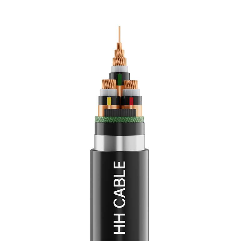 10kV XLPE Insulated Power Cable For Tram Power Supply System EngineeringProduct Name: 10kV XLPE insulated power cable for tram power supply system engineeringView Product →
A Six-Step Selection Sequence That Survives Audit
Worked in order, these steps produce a specification that can be defended in a design review, a factory acceptance test and a warranty claim alike.
Step 1 — Fix the voltage designation. State U0/U (Um) explicitly and confirm how the system neutral is earthed. This single decision sets the insulation thickness and the routine test voltage.
Step 2 — Run the thermal calculation. Use IEC 60287 for steady-state rating and IEC 60853 for cyclic duty. Verify soil thermal resistivity rather than assuming 1.0 K·m/W, and account for burial depth, duct grouping and adjacent heat sources.
Step 3 — Size the conductor for both duties. Continuous load current sets the cross-section for normal operation; short-circuit current at 250 °C for the specified duration sets the minimum acceptable conductor. The larger of the two governs.
Step 4 — Choose the sheath and bonding scheme. Single-point, both-end or cross-bonded, and the resulting sheath standing voltage, which is commonly capped near 65 V on accessible metallic parts unless sheath voltage limiters are fitted.
Step 5 — Specify the test evidence. Type test to IEC 60840, prequalification testing where the project demands it, a routine partial discharge and AC test report for every drum, and the accessory supplier's own qualification record.
Step 6 — Lock installation and commissioning. Control bending radius, pulling tension and jointing humidity, then complete an after-installation AC test with partial discharge measurement before the circuit is handed over.
Most projects do not need the highest voltage class available; they need the class that matches the system, delivered with evidence. A 6/35 kV class XLPE cable properly specified and tested will outperform an oversized cable with incomplete documentation every time.
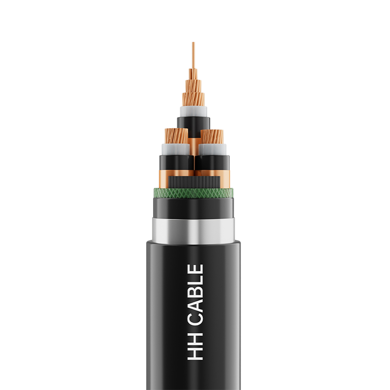 6-35kV Cross-Linked Polyethylene Insulated Power CableProduct Name: 6-35kV cross-linked polyethylene insulated power cableView Product →
Maintenance, Monitoring and the Compliance Paper Trail
Once energised, an HV circuit is monitored rather than inspected. The standard toolset includes:
- Distributed temperature and acoustic sensing along the route, which converts the cable into its own rating sensor and detects third-party excavation activity.
- Online partial discharge monitoring at joints and terminations, where discharge activity appears months before a failure.
- Periodic inspection of sheath voltage limiters, link boxes and bonding connections, since sheath circulation faults raise losses before they raise alarms.
- A thermal rating review whenever load patterns, soil conditions or adjacent heat sources change along the corridor.
Compliance is equally practical. Keep the drum test certificates, the type test reports with witnessed partial discharge data, hot-set elongation and cross-linking records, and material batch traceability in one file tied to the cable route. Quality management, environmental management and occupational health and safety certifications provide the framework, but the project file is what settles a dispute. A cable is only as good as its paperwork the day a warranty claim is filed.
The 110 kV feeder that survives thirty years is not the one with the thickest copper. It is the one whose semiconductor interfaces were controlled during extrusion, whose screen kept moisture away from the insulation, and whose joints were assembled by trained hands under the right conditions — with test data to prove it. Specify those things at tender stage, and the rest of the lifetime cost takes care of itself.
PREV:Types of Electrical Wire: Insulation, Voltage Ratings, and Real-World Use
NEXT:EPR Insulation Explained: Properties, Ratings, and Cable Selection Guide
NEXT:EPR Insulation Explained: Properties, Ratings, and Cable Selection Guide
Interested in cooperation or have questions?
Featured Products
Comprehensive Cable Solutions
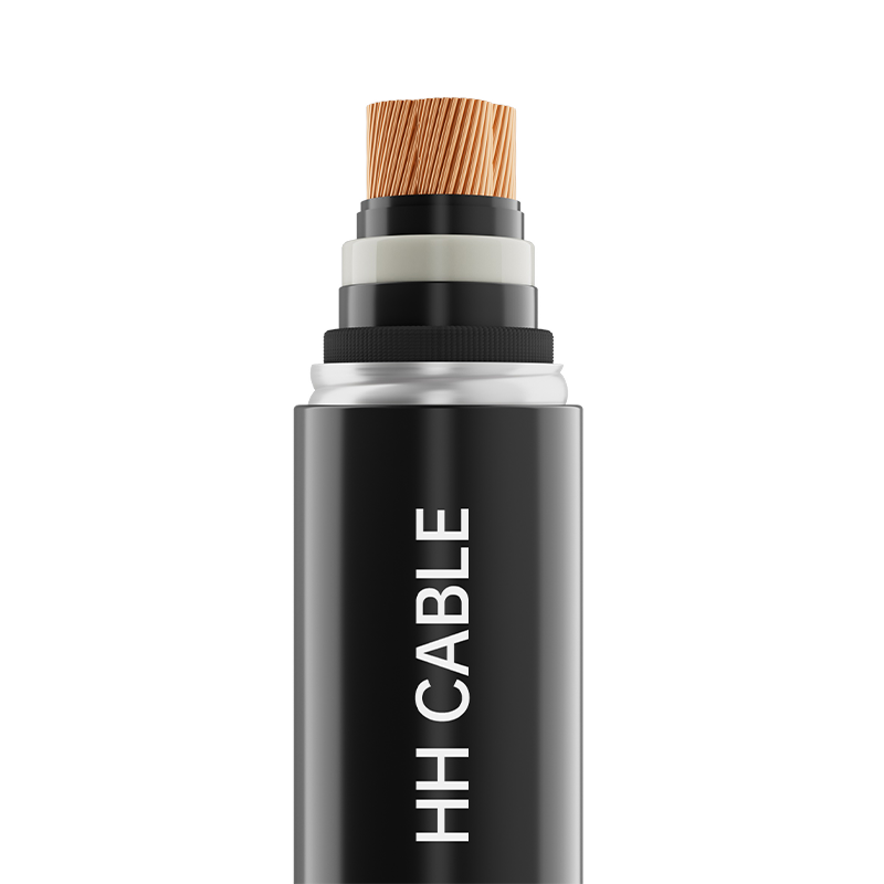
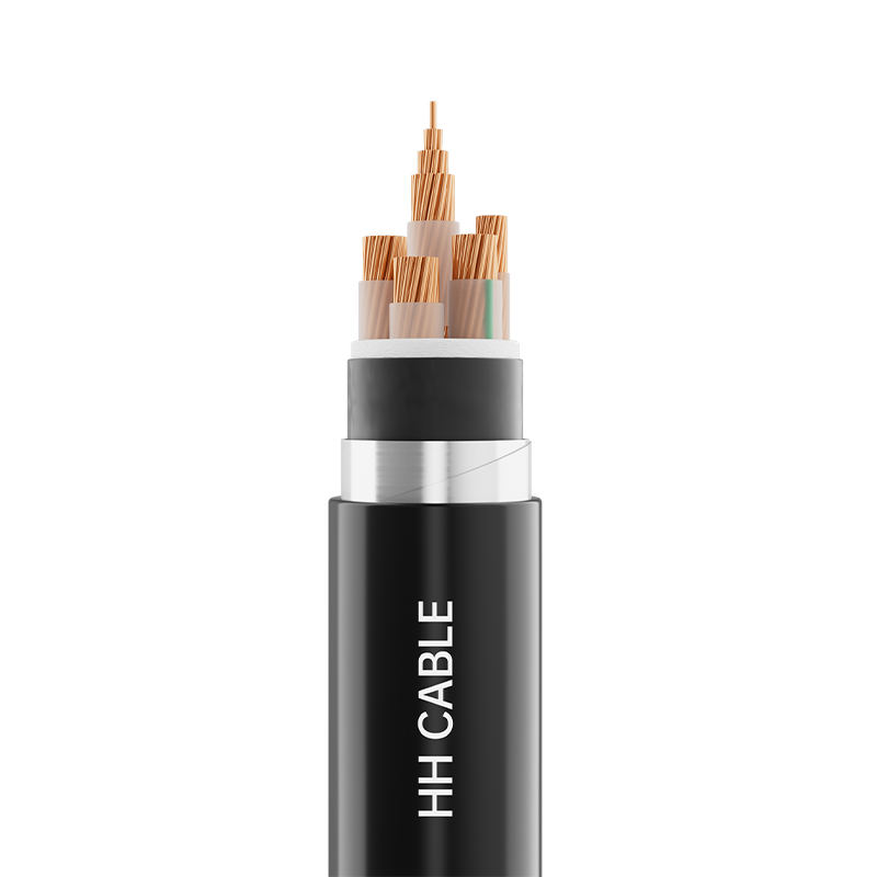
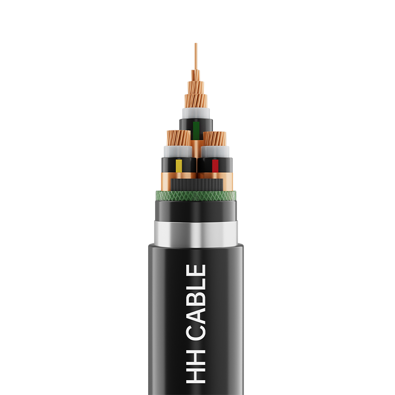


Ready To Customise
Your Cable Products?
Your Cable Products?

Customized Cable Solutions, Bulk Wire Supplier in China. Relying on genuine core quality to build a renowned brand, striving to become a benchmark for advanced
cable standards.
Product Categories
Quick Links
Contact Us
-
Email: [email protected]

-
Mobile: +86-0510-87296815

-
Fax: +86-0510-87295158

-
No. 1, Fengyi Jinfeng Road, Guanlin Town, Yixing City, Jiangsu Province, China

Copyright © Wuxi Henghui Cable Co., Ltd. All Rights Reserved. Custom Cable Manufacturers Electrical Cables Factory
