


 English
 中文简体
中文简体 русский
EPR Insulation Explained: Properties, Ratings, and Cable Selection Guide
EPR Insulation Explained: Properties, Ratings, and Cable Selection Guide
EPR Insulation Explained: Properties, Ratings, and Cable Selection Guide
EPR Insulation Explained: Properties, Ratings, and Cable Selection Guide
EPR Insulation Explained: Properties, Ratings, and Cable Selection Guide
EPR Insulation Explained: Properties, Ratings, and Cable Selection Guide
EPR Insulation Explained: Properties, Ratings, and Cable Selection Guide
EPR Insulation Explained: Properties, Ratings, and Cable Selection Guide
EPR Insulation Explained: Properties, Ratings, and Cable Selection Guide
EPR Insulation Explained: Properties, Ratings, and Cable Selection Guide
EPR Insulation Explained: Properties, Ratings, and Cable Selection Guide
EPR Insulation Explained: Properties, Ratings, and Cable Selection Guide
EPR Insulation Explained: Properties, Ratings, and Cable Selection Guide
EPR Insulation Explained: Properties, Ratings, and Cable Selection Guide
EPR Insulation Explained: Properties, Ratings, and Cable Selection Guide
EPR Insulation Explained: Properties, Ratings, and Cable Selection Guide

Industry News
Home / News / Industry News / EPR Insulation Explained: Properties, Ratings, and Cable Selection Guide
Product Category
NEW Category
Contact us
 +86-0510-87296815
EPR Insulation Explained: Properties, Ratings, and Cable Selection Guide
Picture a 15 kV feeder running through a wet duct bank under a river crossing. When that circuit fails after twelve years, the conductor is rarely the problem. Moisture has worked its way into the insulation and grown into a water tree, or a partial discharge site has slowly eroded the dielectric from the inside out. EPR insulation exists mainly to make both of those failure modes less likely.
The conclusion first: EPR, or ethylene propylene rubber, earns its price premium where moisture, repeated flexing and a punishing thermal duty cycle dominate the design. It is normally specified at voltages up to roughly 35 kV, with a small number of designs reaching 69 kV. It is not a blanket upgrade over cross-linked polyethylene. On dry, steady-load routes in the same voltage band, and on anything above 69 kV, XLPE stays the cheaper and technically stronger answer.
Content
The short version
- EPR is a filled, peroxide-cured elastomer: flexible across a wide temperature band and notably resistant to corona and partial discharge.
- Water treeing resistance is its strongest technical argument on wet, continuously energized circuits.
- Standard MV-105 designs run at 105 °C continuously, 140 °C under emergency overload and 250 °C under short circuit.
- Dielectric loss is higher than XLPE's, which is why EPR stops being practical at the top of the medium-voltage range.
- Budget for a purchase premium and longer lead times than a stocked XLPE item.
None of that makes EPR a niche product. It simply means the specification decision should be driven by the environment the cable will actually live in, not by a material ranking borrowed from another project.
How EPR Insulation Is Built and Why It Behaves Differently
A compound, not a single polymer
EPR is a copolymer of ethylene and propylene, and the EPDM variant adds a third monomer so the material can be cross-linked properly. What reaches the extruder, however, is not the polymer alone. The compound also carries a dielectric-grade clay filler, antioxidants and a peroxide curing system. The filler is the detail most people overlook: it stiffens the rubber slightly, but it also blocks the microscopic channels that develop into water trees, and it changes how the surface reacts to electrical discharge.
The four properties that drive real specifications
Partial discharge and corona resistance
Erosive discharge attacks a filled rubber far more slowly than it attacks a homogeneous thermoplastic. Where voids or voltage spikes cannot be engineered out completely, that difference shows up as service life rather than as a test certificate.
Water treeing resistance
Continuous wet service is the classic EPR case. The material resists the diffusion and cavitation sequence behind water trees, so the designer is not relying on tree-retardant additives as the only defence.
Flexibility across temperature
EPR stays workable well below freezing, which matters for winter pulls, tight bends in trays, and cables that flex repeatedly on reels, festoons or mobile plant.
Thermal headroom
An MV-105 rated EPR insulation carries 105 °C continuously and tolerates 140 °C in emergency overload, which suits circuits whose load follows a production schedule rather than a smooth daily curve.
Corona tolerance also explains why rubber-based constructions appear in inverter-fed drive circuits, where fast switching edges generate repetitive voltage spikes and localized discharge activity. Not every project can absorb the EPR premium for that duty, and a well-built XLPE alternative still performs if the construction is designed around it. A rated voltage 1kV variable frequency power cable with symmetrical, shielded cores is a typical example of that approach.
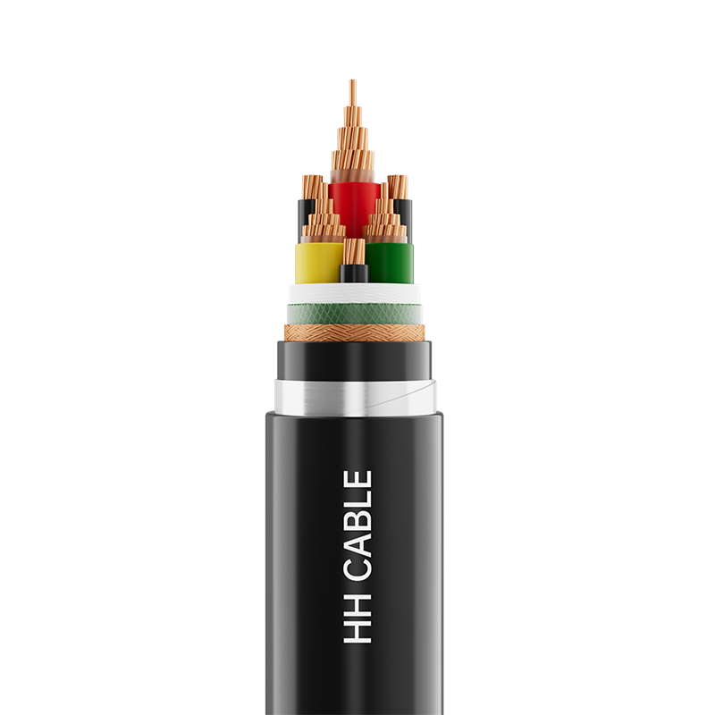 Rated Voltage 1kV Variable Frequency Power CableProduct Name: Rated voltage 1kV variable frequency power cableView Product →
The practical test is simple: if the discharge risk comes from the environment and cannot be removed, pay for the rubber. If it comes from a converter and can be managed by construction and shielding, the cost argument usually favours the thermoplastic.
EPR vs XLPE: Where Each One Earns Its Place
Data sheets rarely make the trade-off obvious, because the two materials are compared on different pages. The comparison below puts the specification-relevant differences side by side.
Property
EPR insulation
XLPE insulation
Relative permittivity
Roughly 3.0 to 3.5
Roughly 2.3
Water treeing resistance
High; the filled rubber structure limits tree growth
Moderate in standard grades; improved with tree-retardant compounds
Corona and partial discharge
High resistance; erosion is comparatively slow
Lower resistance; voids and spikes do more damage
Low-temperature flexibility
Workable well below -30 °C and under repeated flexing
Adequate for fixed installation; stiffer in dynamic duty
Continuous conductor temperature
105 °C in MV-105 designs
90 °C in standard designs
Emergency overload
140 °C
130 °C
Practical voltage ceiling
About 35 kV, occasionally 69 kV
Up to 500 kV
Jointing sensitivity
Slightly more forgiving of field conditions
Demands clean, dry, closely controlled jointing
Purchase cost and lead time
Higher cost; often made to order
Lower cost; frequently available from stock
Table 1: Specification-relevant differences between EPR and XLPE insulation. Figures reflect typical commercial medium-voltage designs, so confirm the exact values against the governing standard and the manufacturer data sheet before tender.
On a dry, ducted 10 kV urban feeder where the load is predictable, the premium is hard to defend, and a standard cross-linked polyethylene construction is the sensible baseline. A 635kV crosslinked polyethylene insulated power cable for distribution duty is a good example of the type that carries most of that work.
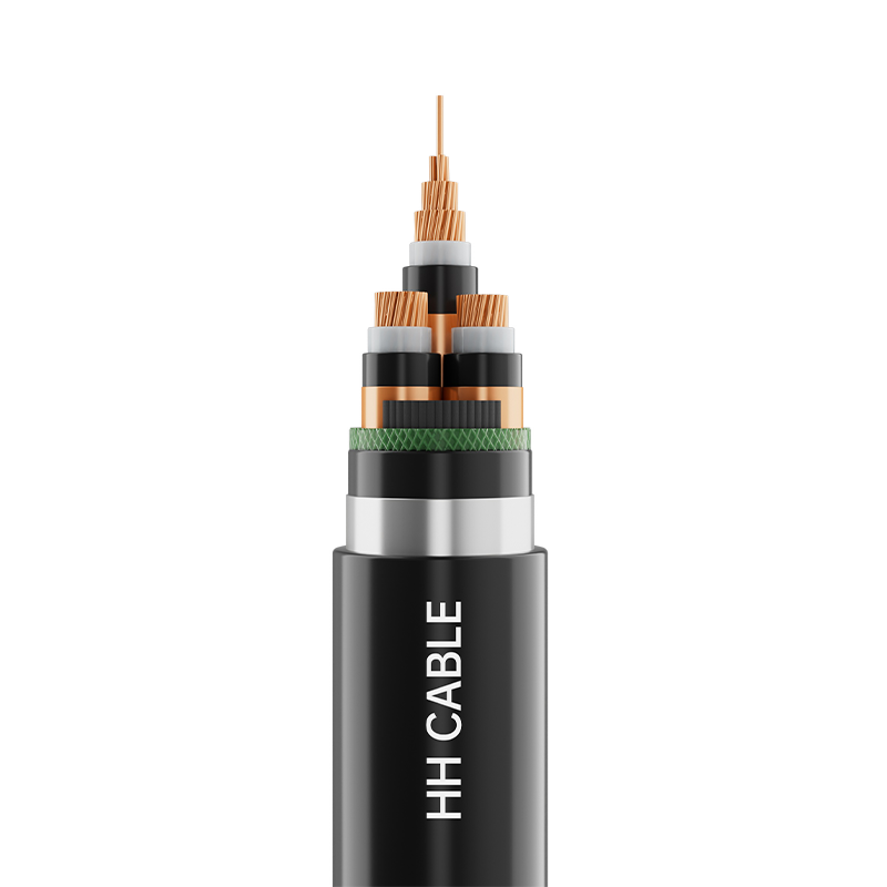 6-35kV Cross-Linked Polyethylene Insulated Power CableProduct Name: 6-35kV cross-linked polyethylene insulated power cableView Product →
Hidden Metrics: How the Two Dielectrics Age in Service
Laboratory type tests do not tell you much about year fifteen. The relative indices below summarize the ageing behaviour discussed in standards literature and manufacturer technical notes, on a scale where a higher bar means a more favourable behaviour for the cable owner.
Water treeing resistance
Corona and PD resistance
Cold flexibility
Thermal headroom
Dielectric efficiency
EPR insulation
XLPE insulation
Read the chart for direction, not for decimals. The point it makes is that EPR's advantage is concentrated in ageing mechanisms driven by water, discharge and movement, while XLPE's advantage sits in dielectric efficiency, which becomes decisive as voltage and circuit length rise.
Where EPR Insulation Is Actually Used
EPR demand is not spread evenly across the grid. It clusters in applications where the cable is wet, moving, or both. The distribution below is an indicative picture of where EPR-based constructions are specified worldwide, offered for orientation rather than as a market study.
Mining, port and portable power equipment — 28%
Medium-voltage distribution, 5 to 35 kV — 26%
Industrial plant and harsh environments — 18%
Rail, tunnel and transit infrastructure — 12%
Renewable generation and storage DC circuits — 9%
Marine and offshore — 7%
Trailing cables on draglines, reeling cables on shiploaders, submersible pump feeders and mining distribution all share the same profile: constant movement, frequent wetting, and a load that refuses to stay polite. Permanently installed supply feeders behave differently. A tram power supply route, for instance, is fixed, usually ducted or buried, and rarely flexed, so the standard choice there is a 10kV XLPE insulated power cable for tram power supply systems rather than a rubber-insulated design.
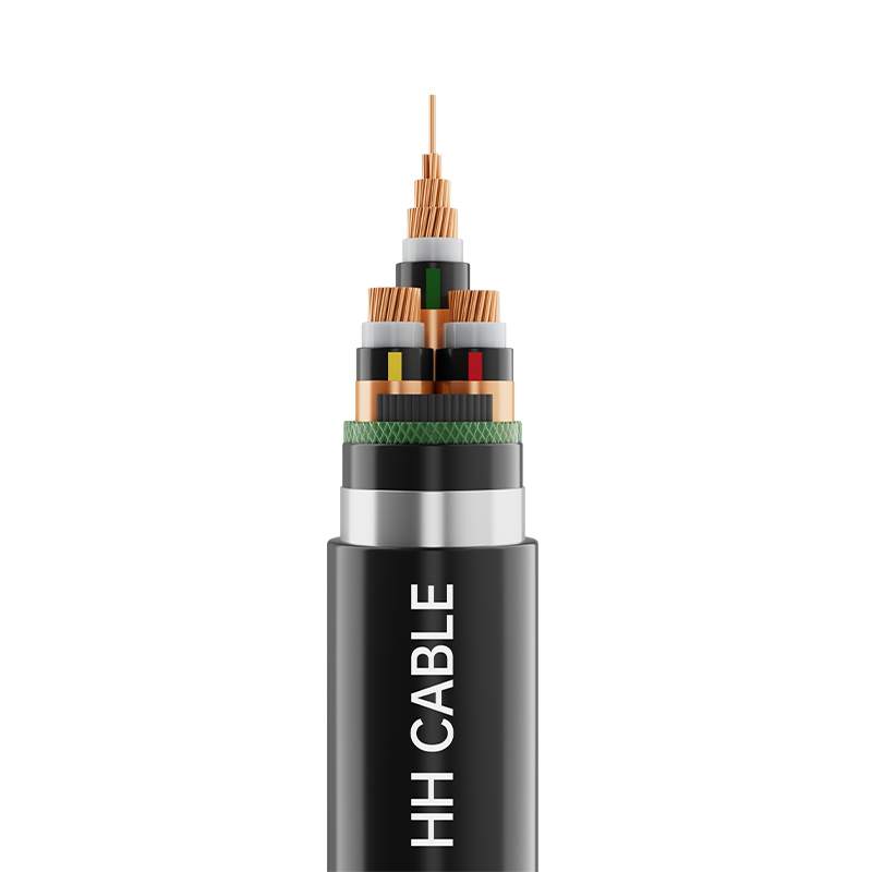 10kV XLPE Insulated Power Cable For Tram Power Supply System EngineeringProduct Name: 10kV XLPE insulated power cable for tram power supply system engineeringView Product →
The same logic applies in process plants, where the flexible, movable, damp sections lean toward rubber and the long fixed runs stay with XLPE. If your circuits sit in a hazardous area, the surrounding design rules matter as much as the insulation itself, and the notes on instrumentation and control circuits in hazardous industrial zones are worth reading alongside the material selection.
A Seven-Step Selection Process
Insulation selection fails most often not because the wrong material was chosen, but because the duty was never written down properly. Working through these steps in order prevents most of the expensive rework.
- Define the duty before the dielectric. Continuous current, ambient temperature, overload profile, short-circuit level, and the failure modes you genuinely expect on that route.
- Score the water and discharge risk. Wet, ducted and submerged routes push the decision toward EPR; dry indoor runs rarely justify the premium.
- Compare temperature classes honestly. The gap between 105 °C and 90 °C insulation converts into an ampacity gain that is often in the region of 8 to 12 percent — but only if the load profile actually uses it.
- Check the installation envelope. Minimum bend radius, maximum pulling tension, and the lowest temperature at which the crew will be pulling the cable.
- Fix the test regime in advance. Agree the routine partial discharge and voltage tests, the sampling frequency, and who witnesses them before the purchase order is issued.
- Lock in the jointing system. Cable and accessories should come from one design family, and the jointers should have verifiable experience with that specific construction.
- Collect the compliance file. Standard conformance, lead-free formulation statements and per-drum routine test certificates, filed against the drum numbers on site.
Steps four and six are where projects lose the most time. A cable that meets every electrical requirement but cannot be pulled around the last bend, or jointed by the crew on site, is not a successful purchase. Before freezing a specification, it also helps to review the full cable range available from a single supplier, so that voltage classes and accessories are matched rather than assembled from unrelated sources.
Maintenance, Testing and Compliance
EPR insulation is tolerant, but it is not maintenance-free. Partial discharge activity is the earliest reliable warning of degradation in both EPR and XLPE, and periodic PD monitoring or a well-executed offline measurement will usually reveal a problem long before a fault occurs. Dielectric loss trending adds a second, slower indicator, particularly useful on circuits that have already seen a decade of wet service.
- Keep field acceptance testing alternating-current or very low frequency rather than direct current; DC testing of extruded dielectrics can leave space charge that distorts the field distribution afterwards.
- Seal cable ends during storage, keep drums out of prolonged direct sunlight, and avoid sharp bends when the insulation is cold.
- Confirm that the compound is a modern lead-free formulation and holds the relevant RoHS and REACH declarations, since legacy rubber compounds in some markets relied on additives that are no longer acceptable.
- Check the governing standard for the voltage class: IEC 60502-2 for the 6 to 30 kV band, IEC 60840 above it, AEIC CS8 or ICEA S-93-639 for North American medium-voltage practice, and EN 50618 for photovoltaic DC cables.
The rule worth carrying into your next specification meeting is straightforward. Choose EPR for the wet, the moving and the thermally stressed; choose XLPE for the dry, the fixed and the high-voltage; and never let the insulation line be the one nobody checked.
PREV:No previous article
NEXT:Does THHN Wire Need to Be in Conduit? NEC Rules, Exceptions & Safe Installation
NEXT:Does THHN Wire Need to Be in Conduit? NEC Rules, Exceptions & Safe Installation
Interested in cooperation or have questions?
Featured Products
Comprehensive Cable Solutions


Ready To Customise
Your Cable Products?
Your Cable Products?

Customized Cable Solutions, Bulk Wire Supplier in China. Relying on genuine core quality to build a renowned brand, striving to become a benchmark for advanced
cable standards.
Product Categories
Quick Links
Contact Us
-
Email: [email protected]

-
Mobile: +86-0510-87296815

-
Fax: +86-0510-87295158

-
No. 1, Fengyi Jinfeng Road, Guanlin Town, Yixing City, Jiangsu Province, China

Copyright © Wuxi Henghui Cable Co., Ltd. All Rights Reserved. Custom Cable Manufacturers Electrical Cables Factory
