


 English
 中文简体
中文简体 русский
Industrial Electrical Cable Guide: Ratings, Derating, and Selection Tips
Industrial Electrical Cable Guide: Ratings, Derating, and Selection Tips
Industrial Electrical Cable Guide: Ratings, Derating, and Selection Tips
Industrial Electrical Cable Guide: Ratings, Derating, and Selection Tips
Industrial Electrical Cable Guide: Ratings, Derating, and Selection Tips
Industrial Electrical Cable Guide: Ratings, Derating, and Selection Tips
Industrial Electrical Cable Guide: Ratings, Derating, and Selection Tips
Industrial Electrical Cable Guide: Ratings, Derating, and Selection Tips
Industrial Electrical Cable Guide: Ratings, Derating, and Selection Tips
Industrial Electrical Cable Guide: Ratings, Derating, and Selection Tips
Industrial Electrical Cable Guide: Ratings, Derating, and Selection Tips
Industrial Electrical Cable Guide: Ratings, Derating, and Selection Tips
Industrial Electrical Cable Guide: Ratings, Derating, and Selection Tips
Industrial Electrical Cable Guide: Ratings, Derating, and Selection Tips
Industrial Electrical Cable Guide: Ratings, Derating, and Selection Tips
Industrial Electrical Cable Guide: Ratings, Derating, and Selection Tips

Industry News
Home / News / Industry News / Industrial Electrical Cable Guide: Ratings, Derating, and Selection Tips
Product Category
NEW Category
Contact us
 +86-0510-87296815
Industrial Electrical Cable Guide: Ratings, Derating, and Selection Tips
A plant electrician replaces the same control cable every eleven months. The conductor size is correct, the load has not changed, and the terminations look clean. The failure is almost never the copper. It is the jacket, the shield, or a derating factor nobody applied when the cable schedule was written.
Industrial electrical cable is specified by a set of numbers rather than a single one. Getting those numbers right at the quotation stage costs nothing. Getting them wrong reappears later as unplanned downtime, re-termination labour, and a second purchase order two years after commissioning.
The short version: specify industrial cable by four parameters — voltage class, continuous ampacity after derating, shielding effectiveness, and jacket material. Ambient temperature, tray fill, and bend radius then decide whether the cable reaches ten years of service or ten months.
The sections below cover how industrial cable differs from building wire, how the common constructions compare, the derating arithmetic that is usually skipped, and a selection sequence you can hand to a supplier as a written specification.
Content
What Separates Industrial Cable From Building Wire
Building wire is chosen for a fixed load in a stable environment. Industrial cable is chosen for a load that varies, in a space that contains heat, vibration, oil mist, moisture, and electrical noise. Four construction choices carry most of that difference.
Conductor stranding
Flexible Class 5 stranding absorbs vibration and repeated flexing at moving equipment. Solid conductors crack at the termination after enough cycles.
Insulation compound
XLPE holds its properties to 90 °C continuous and roughly 250 °C on short circuit. PVC is limited to 70 °C and softens sooner under sustained load.
Shielding
Foil, braided, or combined shields control noise coupling next to drives, radios, and switching devices. An unshielded core has no defence against it.
Jacket compound
Oil-resistant, flame-retardant, or halogen-free jackets determine chemical survival and what happens to the cable during a fire.
- Voltage class is written as U0/U, for example 450/750 V for control cable and 0.6/1 kV for power and drive cable.
- Temperature range belongs to the compound, not to the copper. Two cables with identical conductors can differ by 20 °C in rating.
- Standards scope differently, so IEC, EN, GB, and TUV versions of the same product are not automatically interchangeable on a purchase order.
Comparing the Main Industrial Cable Constructions
Most cable schedules are built from four or five families. The comparison below focuses on the points that drive failure in service rather than on catalogue weight.
The most frequent error is running an ordinary unshielded control cable between a variable-frequency drive and its motor. The switching frequency couples onto the conductors and radiates. A symmetrical shielded construction with a properly bonded gland removes most of it. The same logic applies to low-level analogue signals, where a twisted-pair, foil-shielded cable with a drain wire keeps noise out of 4–20 mA loops. Guidance on instrumentation cables in hazardous industrial zones covers the earthing and barrier details that go with that decision.
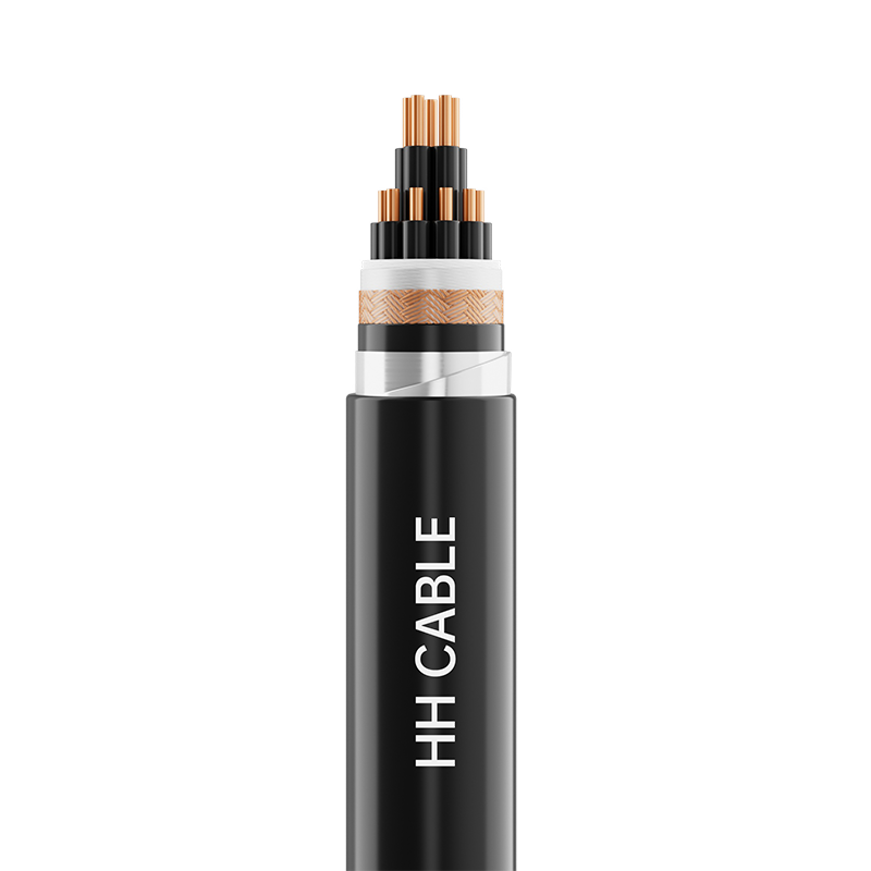 450/750V XLPE Insulated Control CableA 450/750V control cable for monitoring circuits, available with shielding or armor where VFD noise and installation conditions demand more than ordinary unshielded cable.View Product →
Hidden Metrics: Derating Changes Real Ampacity
Published ampacity tables assume free air, a single circuit, and 30 °C ambient. Almost no industrial installation matches all three at once. Ambient temperature and grouping are the two corrections that matter most, and they multiply rather than add.
30.0 A
Free air, 30 °C
24.2 A
Grouped tray, 30 °C
19.5 A
Free air, 60 °C
15.6 A
Grouped tray, 60 °C
The arithmetic is unforgiving. A 2.5 mm² copper conductor rated at 30 A in free air delivers roughly 15.6 A once it sits in a tray with six other loaded cables in a 60 °C ambient — about 48 percent less. Sizing from the catalogue column instead of the corrected figure is one of the most common causes of hardened jackets and early insulation failure, and it stays invisible until the cable is already pulled and terminated.
Voltage drop is the second hidden limit. On runs beyond roughly 50 m, drop frequently decides the cross-section before ampacity does. Calculate both and take the larger result.
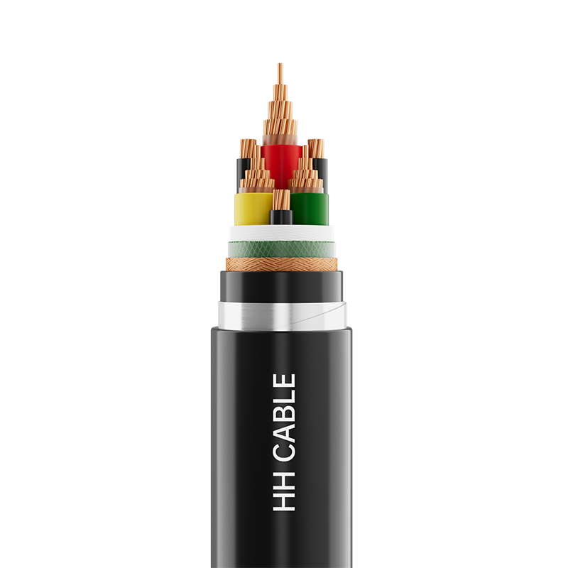 1kV Variable Frequency Power Cable for MotorsFor 0.6/1kV variable-frequency motor circuits, this shielded power cable addresses high-frequency interference and voltage-drop-sensitive runs where cross-section selection must be calculated.View Product →
Where Industrial Cable Is Actually Used
Cable consumption inside a process plant is not evenly spread. A representative cable schedule usually breaks down roughly along the following lines.
Motor and drive circuits — 34%
Control and instrumentation — 26%
Power distribution feeders — 22%
Hazardous and process areas — 12%
Other fixed wiring — 6%
Drive circuits dominate because inverter output is the harshest electrical environment in most plants: high dv/dt, reflected waves on long motor leads, and continuous flexing at the machine. Control and instrumentation cable follows, driven by panel-to-field signalling where a few millivolts of induced noise can trigger a false trip.
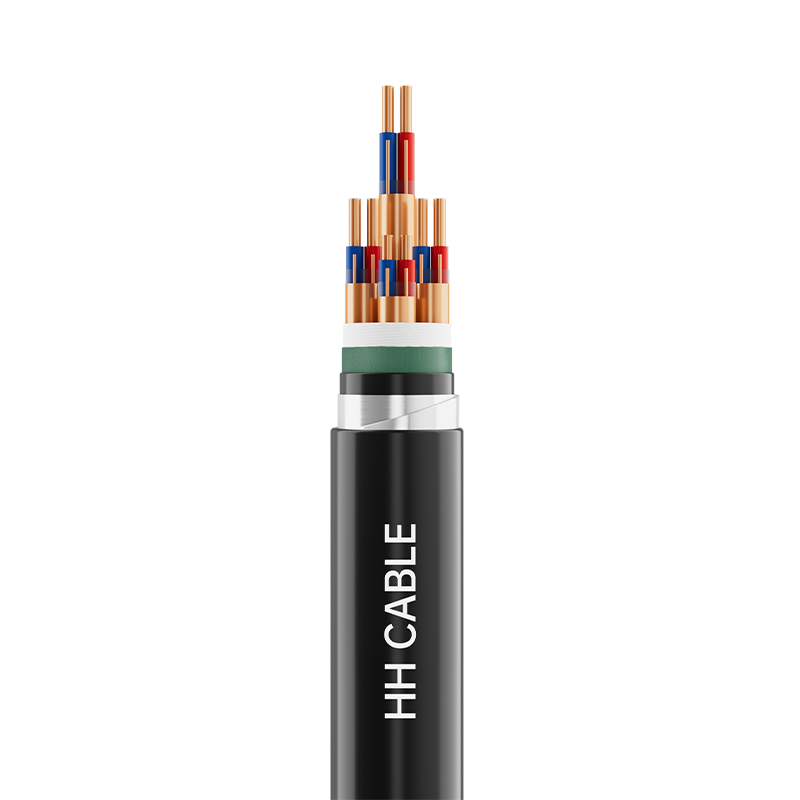 300/500V Computer and Instrument CableFor panel-to-field analogue and digital signals, this 300/500V instrument cable provides shielding, armoring, and fire-resistant options to reduce induced noise and false trips.View Product →
Selection Guide: From Load Data to Purchase Order
Working through these six steps in order prevents the usual rework loop, where a cable is bought, installed, and then replaced because one parameter was assumed rather than calculated.
Step 1 — Define the load and duty cycle
Continuous current, starting current, harmonics, and how often the machine cycles. A duty cycle under 40 percent changes the thermal calculation considerably.
Step 2 — Set the voltage class with margin
0.6/1 kV covers most low-voltage industrial work. Step up when the drive DC bus or the system earthing arrangement demands it.
Step 3 — Fix insulation and jacket by environment
Hot bays and high continuous load point to XLPE. Oil, coolant, or UV exposure narrows the jacket compound choice before anything else does.
Step 4 — Decide on shielding
Drive output, analogue signals, and cables sharing tray with switching equipment require a shield. Bond it at both ends for drive cable and at the signal end for instrumentation.
Step 5 — Apply derating and check voltage drop
Correct for ambient and grouping, then compare against the allowable drop for the circuit. The larger of the two cross-sections wins.
Step 6 — Write the standard and the tests
State the standard, the conductor class, the jacket compound, and the required test reports on the purchase order. Ambiguity here is where substitution happens.
Installation, Testing, and Compliance
A cable that is correct on paper still fails if it is installed badly. The points below cover the recurring issues on industrial sites.
- Respect the minimum bend radius. For XLPE power cable, a working figure is 12 to 15 times the overall diameter, and tighter pulls damage the insulation screen.
- Keep tray fill within the derating assumption. If the fill ratio changes during construction, the ampacity calculation is no longer valid.
- Support cable at intervals that prevent sag and abrasion, especially on vertical runs where the cable weight rests on the top clamp.
- Record insulation resistance and shield continuity before energising, and repeat the same measurements at handover so a trend exists.
- Confirm the flame and smoke requirements for the project: IEC 60332-1 for single-cable flame propagation, IEC 60754 for halogen content, and project-specific low-smoke zero-halogen clauses where they apply.
- Keep type test reports, routine test certificates, and conductor batch traceability on file. On regulated sites, missing documentation can block energisation even when the cable is physically correct.
For projects that span several application types, it helps to consolidate the specification against a single supplier's industrial cable range so that conductor classes, jacket compounds, and test documentation stay consistent from panel wiring through to the motor feeder.
The cables that survive in industrial service are rarely the ones with the highest headline rating. They are the ones where voltage class, derated ampacity, shielding, and jacket compound were all specified together against the real installation conditions. That specification work takes an hour at the quotation stage and is very expensive to repeat after commissioning.
PREV:No previous article
NEXT:Types of Electrical Wire: Insulation, Voltage Ratings, and Real-World Use
NEXT:Types of Electrical Wire: Insulation, Voltage Ratings, and Real-World Use
Interested in cooperation or have questions?
Featured Products
Comprehensive Cable Solutions


Ready To Customise
Your Cable Products?
Your Cable Products?

Customized Cable Solutions, Bulk Wire Supplier in China. Relying on genuine core quality to build a renowned brand, striving to become a benchmark for advanced
cable standards.
Product Categories
Quick Links
Contact Us
-
Email: [email protected]

-
Mobile: +86-0510-87296815

-
Fax: +86-0510-87295158

-
No. 1, Fengyi Jinfeng Road, Guanlin Town, Yixing City, Jiangsu Province, China

Copyright © Wuxi Henghui Cable Co., Ltd. All Rights Reserved. Custom Cable Manufacturers Electrical Cables Factory
