


 English
 中文简体
中文简体 русский
Instrumentation Cable: Types, Specs & Selection
Instrumentation Cable: Types, Specs & Selection
Instrumentation Cable: Types, Specs & Selection
Instrumentation Cable: Types, Specs & Selection
Instrumentation Cable: Types, Specs & Selection
Instrumentation Cable: Types, Specs & Selection
Instrumentation Cable: Types, Specs & Selection
Instrumentation Cable: Types, Specs & Selection
Instrumentation Cable: Types, Specs & Selection
Instrumentation Cable: Types, Specs & Selection
Instrumentation Cable: Types, Specs & Selection
Instrumentation Cable: Types, Specs & Selection
Instrumentation Cable: Types, Specs & Selection
Instrumentation Cable: Types, Specs & Selection
Instrumentation Cable: Types, Specs & Selection
Instrumentation Cable: Types, Specs & Selection
Industry News
Product Category
NEW Category
Contact us
 +86-0510-87296815
Instrumentation Cable: Types, Specs & Selection
In industrial automation, process control, and measurement systems, the reliability of the data traveling through a cable is just as important as the sensor generating it. Instrumentation cable — sometimes referred to as instrument cable — is the specialized conductor designed to carry low-level electrical signals from sensors, transducers, and meters to monitoring, control, and recording systems without distortion or interference. Unlike power cables, which prioritize current-carrying capacity, instrumentation cables are engineered around signal integrity: low capacitance, high insulation resistance, and effective shielding are the defining parameters that separate a well-specified instrument cable from one that will introduce measurement error into a critical process.
Content
- 1 What Instrumentation Cable Is Designed to Do
- 2 Key Electrical Parameters That Define Cable Performance
- 3 Shielding Types and Their Role in Signal Protection
- 4 Multi-Core Designs and the Separation of Power and Signal
- 5 Common Applications of Instrumentation Cable
- 6 Installation Practices That Protect Signal Integrity
What Instrumentation Cable Is Designed to Do
The fundamental purpose of instrumentation cable is to transmit accurate, low-level signals over distances that would otherwise expose the signal to degradation from electrical noise, capacitive loading, and electromagnetic interference. In a typical industrial facility, instrument cables run alongside power cables, variable frequency drives, motors, and other high-energy equipment — all of which generate electromagnetic fields capable of inducing false signals into unprotected conductors.
The signals carried by instrument cables are often in the millivolt or milliamp range. A 4–20 mA current loop signal, for example, represents the full measurement span of a field instrument — from minimum to maximum process value. Any noise or interference injected into that signal introduces a proportional measurement error that propagates through the control system, potentially causing incorrect process adjustments, false alarms, or unsafe operating conditions. This is why the electrical characteristics of the instrumentation cable itself — not just its physical dimensions — must be carefully matched to the application.
Key Electrical Parameters That Define Cable Performance
Selecting the right instrumentation cable begins with understanding the electrical parameters that govern its signal transmission performance. Three properties are central to this assessment: capacitance, insulation resistance, and conductor resistance.
Capacitance
Capacitance in a cable is the ability of adjacent conductors, separated by insulation, to store electrical charge. In signal cables, high capacitance acts as a low-pass filter — it attenuates high-frequency signal components and slows the rise time of rapidly changing signals. For instrumentation applications involving fast-responding sensors, high-speed data acquisition, or pulse signals, low capacitance per unit length is essential. Well-designed instrument cables typically specify conductor-to-conductor capacitance values in the range of 50 to 120 picofarads per meter, with the exact target depending on cable length and signal frequency requirements.
Insulation Resistance
Insulation resistance measures how effectively the insulating material around each conductor prevents leakage current between conductors or from conductor to shield or earth. In humid industrial environments — particularly in chemical plants, water treatment facilities, and offshore installations — moisture ingress into cable insulation is a persistent risk. High insulation resistance, typically specified in gigaohms per kilometer, ensures that leakage currents remain negligibly small even under demanding environmental conditions. Cross-linked polyethylene (XLPE) and fluoropolymer insulations offer superior moisture resistance compared to standard PVC, making them the preferred choice in demanding instrumentation applications.
Conductor Resistance
While conductor resistance is less critical in instrumentation cables than in power cables, it still affects the performance of current loop and bridge circuit signals. Higher conductor resistance creates a larger voltage drop along the cable run, which can reduce the available compliance voltage in a 4–20 mA loop or introduce offset errors in bridge circuits. For long cable runs — particularly those exceeding 300 meters — using a larger conductor cross-section to reduce resistance is a practical and cost-effective solution.
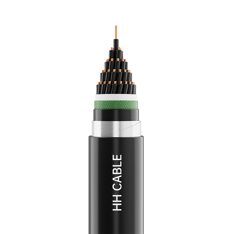
Shielding Types and Their Role in Signal Protection
Shielding is the single most important structural feature that distinguishes instrumentation cable from general-purpose wiring. An effective shield intercepts electromagnetic interference before it reaches the signal conductors, providing a controlled path for induced currents to flow harmlessly to earth. Instrumentation cables are available with several shielding configurations, each suited to different interference environments.
| Shield Type | Construction | Coverage | Best Application |
| Aluminum/Polyester Foil | Laminated foil wrap with drain wire | 100% | General EMI/RFI protection |
| Braided Shield | Woven tinned copper braid | 85–98% | High-flex, mechanical protection |
| Combined Foil + Braid | Foil inner layer + braid outer layer | 100% (foil) + mechanical | Severe EMI environments |
| Individual Pair Screen | Each pair screened separately | 100% per pair | Multi-channel, crosstalk-sensitive |
Individual pair screening is particularly important in multi-core instrumentation cable designs where multiple independent signal channels share a common outer jacket. Without individual screens, signal crosstalk between adjacent pairs can corrupt measurements, especially where signals of very different amplitudes or frequencies run in parallel. A multi-core cable with individually screened pairs and an overall braid shield offers the highest level of both inter-channel isolation and external EMI rejection — the preferred specification for critical measurement circuits in electrically noisy industrial environments.

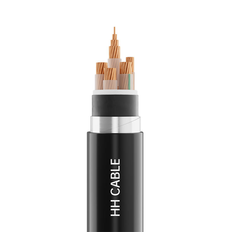
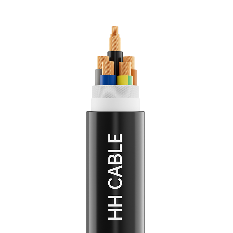
Multi-Core Designs and the Separation of Power and Signal
Multi-core instrumentation cables are designed to carry multiple independent signal circuits within a single outer sheath, simplifying cable management and reducing installation costs in complex systems with many field instruments. However, combining multiple circuits in a single cable introduces the risk of mutual induction — where the magnetic field generated by current in one conductor induces a voltage in adjacent conductors.
In multi-core designs, separating power and signal conductors is a fundamental design principle that minimizes mutual induction. Even low-level power conductors — such as those supplying 24 VDC to field transmitters — should be physically separated from signal pairs within the cable or run in entirely separate cables wherever interference sensitivity is high. When separation within a single cable is used, individual pair screens provide the necessary isolation barrier. Twisting each signal pair also plays a role: the twist pitch cancels out electromagnetically induced noise by ensuring that each half-twist of the pair is exposed to interference in opposite polarity, causing the induced voltages to cancel at the receiver.
Common Applications of Instrumentation Cable
Instrumentation cables serve a vast range of industries and measurement functions. Their consistent requirement across all these applications is signal accuracy under environmental and electrical stress — the specific construction details vary by industry and installation conditions.
- Oil and Gas: Connecting pressure transmitters, temperature sensors, flow meters, and level gauges to distributed control systems (DCS) and safety instrumented systems (SIS) in refineries, pipelines, and offshore platforms. Cables in these environments require flame-retardant or fire-resistant outer sheaths and often armoring for mechanical protection.
- Chemical Processing: Carrying analytical instrument signals from pH sensors, conductivity meters, and gas analyzers in environments with chemical vapors and high humidity. Chemical-resistant jacket materials such as PVDF or fluoropolymer are specified where cable surfaces may contact aggressive substances.
- Power Generation: Transmitting thermocouple and RTD signals from turbine and boiler temperature measurement points to control room monitoring systems over long cable runs, where low capacitance and high insulation resistance are critical to maintaining signal accuracy.
- Water and Wastewater Treatment: Connecting flow, level, and quality sensors in wet, corrosive environments where UV resistance and waterproof jacket materials extend service life and reduce maintenance frequency.
- Building Automation and HVAC: Carrying signals from temperature, pressure, and occupancy sensors to building management systems, where fire performance ratings and low-smoke, zero-halogen (LSZH) jacket materials are commonly required.
Installation Practices That Protect Signal Integrity
Even the best-specified instrumentation cable will underperform if installation practices compromise its electrical design. Shield grounding is the most frequently mishandled aspect of instrument cable installation. A shield must be grounded at one end only — typically at the control room or marshalling panel end — to prevent the shield from carrying circulating currents that would actually introduce noise rather than reject it. Grounding at both ends creates a ground loop: a path for current to flow through the shield driven by the potential difference between the two earth points, which can be substantial in large industrial facilities.
Physical separation from power cables during routing is equally important. Where instrumentation cables must cross power cables, they should do so at 90 degrees rather than running in parallel. Parallel routing over extended distances allows electromagnetic coupling to build up progressively along the cable run. Where separation is impractical, installing instrument cables in dedicated metallic conduit or cable tray with a grounded divider between power and instrument cable trays provides meaningful interference reduction.
Maintaining the integrity of each conductor's twist throughout termination is a detail that is often overlooked but matters in high-sensitivity circuits. Untwisting more than the minimum necessary length of pair to make a termination increases the exposure of the conductors to differential mode interference exactly where the shield ends — the most vulnerable point in the cable run. Neat, tight terminations with minimal untwisted length are the hallmark of professional instrumentation cable installation, and they directly contribute to the measurement accuracy that the entire system depends upon.
PREV: Solar Cable & Photovoltaic Cable Guide
NEXT:How Do IEC, IEEE, and ANSI Standards Differ for Electric Transmission Cables?
NEXT:How Do IEC, IEEE, and ANSI Standards Differ for Electric Transmission Cables?
Interested in cooperation or have questions?
Featured Products
Comprehensive Cable Solutions


Ready To Customise
Your Cable Products?
Your Cable Products?

Customized Cable Solutions, Bulk Wire Supplier in China. Relying on genuine core quality to build a renowned brand, striving to become a benchmark for advanced
cable standards.
Product Categories
Quick Links
Contact Us
-
Email: [email protected]

-
Mobile: +86-0510-87296815

-
Fax: +86-0510-87295158

-
No. 1, Fengyi Jinfeng Road, Guanlin Town, Yixing City, Jiangsu Province, China

Copyright © Wuxi Henghui Cable Co., Ltd. All Rights Reserved. Custom Cable Manufacturers Electrical Cables Factory
